Getting Started with EPS8266-12E Wi-Fi | ESP8266-12E 筆記本
I wanted to test out ESP8266 for a long time. However, I never got it to work until today. There are many tutorials and articles detailed how to make ESP8266 work, but even I followed many of those tutorials step by step mine ESP8266 just didn't work. It was very frustrating not able to figure out what went wrong. Anyway, I got it worked today, so it's better for me to write the steps down, not just for blog visitor like you, but also for myself as a good reference later on.
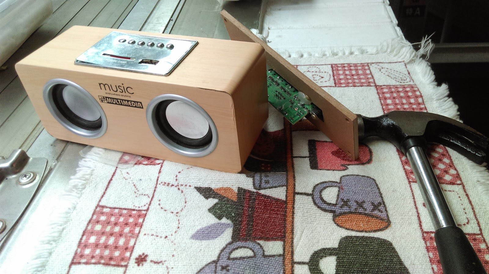
Previous three failed attempts... 😒

Different Version of ESP8266
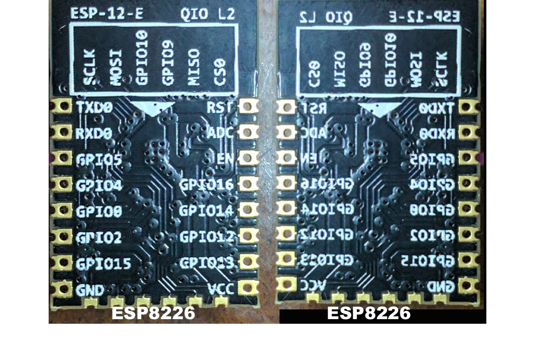
There are many ESP8266 variations, the one I used for this tutorial is ESP8266-12E. Please refer to this page[2] to get more information for ESP8266 variations.ESP8266 Pin Assignment
Most of the people probably will solder ESP8266 with metal covers facing up, so I placed a reversed pin assignment on the right side for easier pin reference.
Material Needed:
- ESP8266-12E * 1
- Perfboard * 1
- Breadboard * 1
- Wires - as many as needed
- Resistors 1K * 4
- CP2102 USB-Serial Converter * 1
Tools Needed:
- Power supply (3.3V)
- Soldering iron
- Solder Tin
- Plier-wire cutter
- Plier
Step One:
ESP8266 has 2mm pin pitch instead of 2.54mm standard pitch. So we have to place it on a prefboard to make connections easier.
Place ESP8266 on a prefboard and draw its relative size that's larger to accommodate pins along both sides for easier connections with DuPoint wires. Cut down the piece of prefboard with a plier.
[Important: I later found out from the ESP8266 datasheet recommended to place Wi-Fi antenna outside of prefboard to get better signal reception & transmission.] 😄
[Important: I later found out from the ESP8266 datasheet recommended to place Wi-Fi antenna outside of prefboard to get better signal reception & transmission.] 😄

Step Two:
Solder wires on each ESP8266 pin to the prefboard as shown below. I found out that after stripped skin of the wires, soldering job just got a little bit easier.
Note: My previous attempt was to solder wires without strip the wire skin and it was more difficult to solder; harder to bend the wires. Be careful, do not short these wires! :)
Note: My previous attempt was to solder wires without strip the wire skin and it was more difficult to solder; harder to bend the wires. Be careful, do not short these wires! :)

Step Three:
Solder 8 pin headers on each side of ESP8266 as shown below.
Step Four:
Time to connect all wires together. Check out the schematic diagram below for all the connections needed.Schematic Diagram
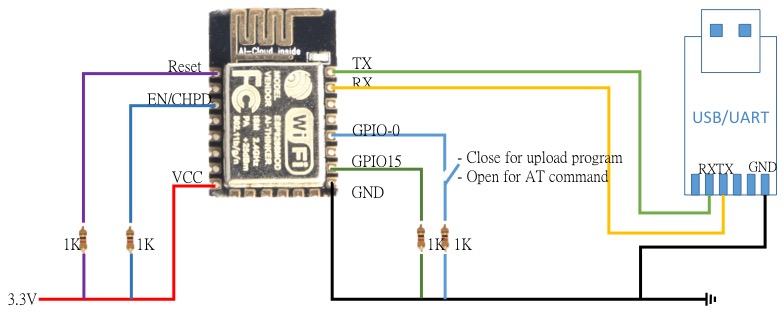
ESP8266 Connection:
- VCC -> 3.3V power source
- EN-CHPD -> 1K resistor -> 3.3V
- Reset -> 1K resistor -> 3.3V
- TX -> USB/UART RX
- RX -> USB/UART TX
- GPIO0 -> do not connect anything for this AT command tutorial
- GPIO15 -> 1K resistor -> GND
- GND -> GND
CP2012 USB/UART Connection
- RX -> ESP8266 TX
- TX -> ESP8266 RX
- GND -> GND (command ground with ESP8266)
NOTE:
- Supply 3.3V to EPS8266! 5V will burn ESP8266!
- GPIO-0 is connected to GND: upload Arduino programming code.
- GPIO-0 is not connected: Enter AT Command.

Step Five:
Here, I used a red breadboard for wire connections with resistors and the power supply. As long as you follow the schematic diagram above and wiring tips for the connection, it shouldn't be too difficult. (I only use two transistors to share with common pins to VCC and GND. Not sure if this is a good practice?)

I have purchased an inexpensive power supply as the 3.3V power source. It displayed the how much the current is using, in this case "068mA", allowing me to see what power was consumed at the particular point of time, which it's very convenient! I checked ESP8266 datasheet "68mA ~ 71mA" means it's working probably.

Step Six:
Test AT Command. I think this is a quick method to check whether the ESP8266 is working or not.
- Connect CP2012 to a Mac USB port
- Power on power supply with 3.3V
Arduino IDE Operations:
- First, let's load ESP8266 Library into Arduino IDE
- Copy this string "http://arduino.esp8266.com/stable/package_esp8266com_index.json" into Arduino IDE preference -> Settings -> Additional Board Manager URLs. See below in yellow highlighted strings.

- Select correct Arduino board type. Select "ESPino (ESP-12 module)" If you don't see this option, please restart Arduino IDE to ensure the library is properly loaded.

- Select Port from port list. My serial port is /dev/cu.SLAB_USBtoUART

- Click [Tools] - [Serial Monitor] from Arduino IDE to open the serial monitor.

- Select baud rate from the baud rate list below. Select [115200 baud]. Your ESP8266 might have default baud rate of 9600 or 38400. If 15200 doesn't work, please try all other baud rate values.

Start AT Command
- AT: You should be able to see the terminal replied "AT OK" back. Congratulation, your ESP8266 is working!

- AT+GMR: Display ESP8266 firmware version. My ESP8266 is V1.2.0.0 Date: Dec 2, 2016.

- AT+CWJAP="Wi-Fi_SSID","Password": Connect to the particular Wi-Fi Access point with the password designated. As you can see, the WiFi got connected immediately.

- AT+CWMODE?[1]: Setup ESP8266 working mode. Let's setup ESP8266 to mode 3 both STA and AP. This allows ESP8266 connecting to your Wi-Fi router/Access point as a client also works as a router/Access point allowing other Wi-Fi client connect to it.
- AT+CWMODE=1: STA (Become a Wi-Fi client to connect to AP)
- AT+CWMODE=2: AP (Become an Assess point, so other clients can connect to this AP)
- AT+CWMODE=3: BOTH = STA + AP (As an access point and a Wi-Fi client)
- AT+CIFSR: Get IP Address. Since we setup CWMODE=3 (STA+AP mode), the first IP you see is AP IP (ESP8266 IP 192.168.4.1), the second IP is the WAN IP(your Wi-Fi IP 192.168.0.105 where ESP8266 is connected to)


- AT+CWLAP: Scan Wi-Fi AP in the nearby area and show them all in a list.
Text in first double quotes are WI-Fi SSID.

- AT+RST: Reset command to reset ESP8266

It's great! Your ESP8266 is ready to connect to the Internet.
Load First Arduino Code:
ESP8266 can be used as an Arduino board itself without buying another Arduino board to work with ESP8266. Let's flash Arduino code into ESP8266 to test it out.
- Connect GPIO0 -> 1K resistor -> GND (Without GPIO0 pull low, you can't flash code to ESP8266!
- Copy the code below into your Arduino IDE and upload the code and the ESP8266-12E
*********************************************************************************
IMPORTANT: After you upload Arduino codes, the AT command will no longer work. If you still prefer use AT command with ESP8266, you have to reflash AT command firmware to enable it.
It took me few days to figure out this!
*********************************************************************************
First Arduino code for ESP8266-12E, Connect to Wifi
This Arduino code below will connect ESP8266 to your WiFi AP/router and display the IP address it obtain. For this code to work, please replace Wifi_SSID with your Wifi-SSID and Wifi_Password with your own Wifi-Password. Do not forget to open Arduino IDE serial port to see the connection message!
#include <ESP8266WiFi.h>

void setup()
{
  Serial.begin(115200);
  Serial.println();

  WiFi.begin("Wifi_SSID", "Wifi_Password");

  Serial.print("Connecting");
  while (WiFi.status() != WL_CONNECTED)
  {
    delay(500);
    Serial.print(".");
  }
  Serial.println();

  Serial.print("Connected, IP address: ");
  Serial.println(WiFi.localIP());
}

void loop() {}
Second Arduino code for ESP8266-12E, Blink
#include <ESP8266WiFi.h>
void setup()
{
  Serial.begin(115200);
  Serial.println();
  pinMode(LED_BUILTIN, OUTPUT);     // Initialize the LED_BUILTIN pin as an output

  WiFi.begin("Wifi-SSID", "Wifi-Password");

  Serial.print("Connecting");
  while (WiFi.status() != WL_CONNECTED)
  {
    delay(500);
    Serial.print(".");
  }
  Serial.println();

  Serial.print("Connected, IP address: ");
  Serial.println(WiFi.localIP());
}

void loop() {
  digitalWrite(LED_BUILTIN, LOW);   // Turn the LED on (Note that LOW is the voltage level
                                    // but actually the LED is on; this is because
                                    // it is acive low on the ESP-01)
  delay(1000);                      // Wait for a second
  digitalWrite(LED_BUILTIN, HIGH);  // Turn the LED off by making the voltage HIGH
  delay(2000);                      // Wait for two seconds (to demonstrate the active low LED)
  }
That's all for this step by stpe notes. Hope you are getting something from here! :)
REFERENCE
- ESP8266 Wi-Fi Library Great info to get more about ESP8266 Wi-Fi Library as well as what's AP, STA, and BOTH modes.
- Various ESP8266 boards Great info to understand the different types of ESP8266.
==============================================================
EPS8266-12E Wi-Fi 筆記
真的很高興,這個部落格在這幾天已經超過30萬的瀏覽次數!謝謝大家拜訪Stonez56的部落格來獲取有對你價值的資訊。😁長久以來,我一直想測試ESP8266,但是一直沒有成功。雖然,網上有很多教學和文章詳細介紹如何使用ESP8266,但即使我跟著很多這些教學一步一步地做,大部份都失敗了。 很多時候無法弄清楚哪裡出了問題,真是令人非常沮喪。 今天我手上的ESP8266已經正常的能回覆 AT Command,所以我趕快把這些步驟寫下來,不只可以提各位讀者參考,以後也可以作為自己的一份筆記。
看看我之前失敗的例子...都堆在角落裡!
不同版本的 ESP8266
市面上有很多不同的版本,請參考這裡[2] 來了解其它ESP8266版本的差異。ESP8266 腳位說明
ESP8266腳位說明如下。 由於大多數人可能會把ESP8266的金屬蓋朝上焊接,所以我在右側放置了一個反向的腳位,以便於大家參考。
所需材料:
- ESP8266-12E * 1
- 洞洞板* 1
- 麵包板* 1
- 電線 - 十多條
- 電阻器1K * 4
- CP2102 USB 轉換器 * 1
所需工具:
- 電源(3.3V)
- 烙鐵
- 焊錫
- 鋼絲鉗
- 鑷子
步驟一:
ESP8266 腳位是 2mm 的間距,而不是2.54mm的標準間距。 所以我們必須把它銲在洞洞板上以方便連接。先將ESP8266放置在洞洞板上,並畫下其相對尺寸較大的尺寸,沿著兩側留下兩三個洞的距離,等會要銲上接腳,便於用杜邦線測試連接。 先用鉗子剪下畫好大小的洞洞板。
[重要說明:我從ESP8266官方文件中發現,Wi-Fi天線不能放在金屬的上方,以便獲得更好的接收信號和處理能力!所以最後我把天線底下的洞洞板都用斜口鉗剪掉!]😄
步驟二:
如下所示,把每個ESP8266的腳位上用電線連接到洞洞板上。我發現電線剝皮後,比較容易焊一些。我看許多網友也都這樣做!注意:我以前的嘗試是焊接電線時沒有剝掉電線的外皮,焊接起來也比較困難; 也較不容易彎曲電線。 但是請小心,不要把這些電線短路! ☺
步驟三:
在ESP8266的兩側焊接上 8 個針腳,如下所示。步驟四:
參考下面的示意圖,把所有電線接好準備測試。Schematic Diagram

ESP8266連接方法:
- VCC - &gt; 3.3V 電源
- EN-CHPD - &gt; 1K 電阻 - &gt;3.3V
- 重置 - &gt; 1K 電阻 - &gt;3.3V
- TX - &gt; USB / UART RX
- RX - &gt; USB / UART TX
- GPIO0 - &gt; 請先不要連接任何腳位,才能做 AT Command 測試
- GPIO15 - &gt; 1K 電阻 - &gt;GND
- GND - &gt;GND
CP2012 USB / UART連接方法:
- RX - &gt; ESP8266 TX
- TX - &gt; ESP8266 RX
- GND - &gt; GND(ESP8266共同接地)
注意:
- EPS8266只能使用 3.3V 電源! 使用5V會燒掉ESP8266!
- GPIO-0連接到GND:可上傳Arduino程式
- GPIO-0未連接:可輸入AT Command
步驟五:
如下圖,我用一個紅色小麵包板用來連接電阻和電源連接。 只要你按照上面的示意圖和接線提示連接即可。 (我只使用兩個 1K 電阻與VCC和GND共用腳位,不知道這是否是一個好的方法?)
我買了一台電源供應器來提供3.3V穩定電源。它也可以顯示目前的電流量,如:“068mA”,讓我知道在特定的時間點,電流量是多少,非常方便! 我查了一下ESP8266的資料“68mA〜71mA”,表示它 Wi-Fi 是開啟中工作中。
步驟六:
測試AT命令。這是一個檢查ESP8266是否正常運作的快速方法。- 將 CP2012 連接到 Mac USB
- 開啟3.3V電源
Arduino IDE使用說明:
- 先讓我們將ESP8266程式資料載入到Arduino IDE 中
- 將此字串 “http://arduino.esp8266.com/stable/package_esp8266com_index.json” 複製到Arduino IDE Preference - &gt; Settings - &gt; Additional Board Manager URLs: 下方我用黃色標出的字符:
- 一定要選擇正確的Arduino類型。 在選單中選擇“ESPino(ESP-12 Module)”如果您沒有看到此選項,請重新啟動一次Arduino IDE以確保ESP8266資料有帶進來。
- 選擇 Port,我的 serial port 設定是 /dev/cu.SLAB_USBtoUART
- 按一下 [Tools] -> [Serial Monitor] 打開序列埠的監看視窗。
- 選擇連接速率 baud rate。 我用的是 [115200 baud]. 您的ESP8266的內建速率可能是9600或38400.如果15200沒法使用,請嘗試所有其他的速率值。
開使使用 AT Command:
- 在最上方的命令列上打 AT,您應該能夠看到監看視窗回答“AT OK”。 恭喜,您的ESP8266已在正常工作中!
- AT+GMR: 顯示 ESP8266 軔體版本. 我的 ESP8266 是 V1.2.0.0 Date: Dec 2, 2016.
- AT+CWJAP="Wi-Fi_SSID","Password": 使用指定的SSID 和 密碼 連接到特定的Wi-Fi分享器或路由器。 監看視窗會顯示,WiFi已連接成功!
- AT+CWMODE?[1]: 設定ESP8266工作模式。讓我們將ESP8266設置為模式3 STA和AP。 這可以讓ESP8266作為客戶端連接到您的Wi-Fi路由器,ESP8266自己也可以作為路由器/,允許其他Wi-Fi客戶端連接到它。
- AT+CWMODE=1: STA (Become a Wi-Fi client to connect to AP)
- AT+CWMODE=2: AP (Become an Assess point, so other clients can connect to this AP)
- AT+CWMODE=3: BOTH = STA + AP (As an access point and a Wi-Fi client)
- AT+CIFSR: 顯示IP位址。 由於我們設置了CWMODE = 3(STA + AP模式),所以您看到的第一個IP是ESP8266自己的 IP(ESP8266 IP 192.168.4.1),第二個IP是連到Internet的路由器 IP(ESP8266 Wi-Fi IP 192.168.0.105)
- AT+CWLAP: 掃描附近區域的Wi-Fi 路由器,並將其全部顯示在列表中。
下方左側第一個雙引號中的文字是各路由器的 SSID。為了安全,我把 mac adress 畫掉了~
- AT+RST: 重置 ESP8266,讓它重新開機!
太好了! 您的ESP8266已準備好連接到Internet。
載入第一個Arduino 程式到 ESP8266:
其實ESP8266可以當作一般Arduino板來使用,它上面也有很多 I/O 腳位,不要再連另一塊 Arduino 來節省成本。 現在我們把Arduino的程式碼載入到ESP8266中進行測試。- 記得連接GPIO0 -&gt; 1K電阻器 - &gt; GND(GPIO0 要 pull low,不然,程式碼無法載入到ESP8266!
- 將以下程式碼複製到您的Arduino IDE並載入到ESP8266-12E裡
*********************************************************************************
重要提示:在您上傳Arduino程碼後,AT命令將不能再使用。 如果您仍然想要使用ESP8266的AT命令,則必須上載AT command 的軔體才能再使用。
*********************************************************************************
重要提示:在您上傳Arduino程碼後,AT命令將不能再使用。 如果您仍然想要使用ESP8266的AT命令,則必須上載AT command 的軔體才能再使用。
*********************************************************************************
第一個 ESP8266-12E 程式,連接到 WiFi AP :
下面這個Arduino程式碼將啟動ESP8266連接到您的WiFi AP /路由器,並顯示它取得的IP地址。 要使用此程式碼,記得把您的Wifi密碼將Wifi_SSID替換為您的Wifi-SSID和Wifi_Password。
#include <ESP8266WiFi.h>

void setup()
{
  Serial.begin(115200);
  Serial.println();

  WiFi.begin("Wifi_SSID", "Wifi_Password");

  Serial.print("Connecting");
  while (WiFi.status() != WL_CONNECTED)
  {
    delay(500);
    Serial.print(".");
  }
  Serial.println();

  Serial.print("Connected, IP address: ");
  Serial.println(WiFi.localIP());
}

void loop()
{}
第二個 ESP8266-12E 程式, 閃爍 ESP8266 內建 LED
#include <esp8266wifi.h>

void setup()
{
  Serial.begin(115200);
  Serial.println();
  pinMode(LED_BUILTIN, OUTPUT);     // Initialize the LED_BUILTIN pin as an output

  WiFi.begin("Wifi-SSID", "Wifi-Password");

  Serial.print("Connecting");
  while (WiFi.status() != WL_CONNECTED)
  {
    delay(500);
    Serial.print(".");
  }
  Serial.println();

  Serial.print("Connected, IP address: ");
  Serial.println(WiFi.localIP());
}

void loop() {
  digitalWrite(LED_BUILTIN, LOW);   // Turn the LED on (Note that LOW is the voltage level
                                    // but actually the LED is on; this is because
                                    // it is acive low on the ESP-01)
  delay(1000);                      // Wait for a second
  digitalWrite(LED_BUILTIN, HIGH);  // Turn the LED off by making the voltage HIGH
  delay(2000);                      // Wait for two seconds (to demonstrate the active low LED)
  }
OK,希望你從這裡能得到你要的一些資訊!:)
參考文件:
- ESP8266 Wi-Fi Library Great info to get more about ESP8266 Wi-Fi Library as well as what's AP, STA, and BOTH modes.
- Various ESP8266 boards Great info to understand the different types of ESP8266.


Comments
Post a Comment