Showing posts with label relay module. Show all posts

2018/02/27

Arduino - Switch celling light with TV remote (2/2)

This is the part two of Switch celling light with TV remote tutorial. If needed, please check out the part one from link below. By the way, the source code is also available there.


Quick Link


System Design

See the illustration below. I used a phone charger(purple block; AC110V to DC5V) to supply power from 110v AC power outlet from the celling. The Arduino controls the relay module to switch the celling light and Arduino interpret IR code to change  RGB LED to shift color and on/off accordingly. 
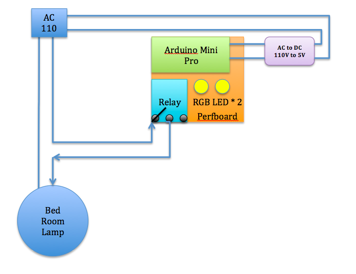
Connections

  • IR Receiver to Arduino pin 2
  • IR Receiver + to VCC
  • IR Receiver - to GND
  • Relay + to VCC
  • Relay - to GND
  • Relay to Arduino pin 8
  • RGB Red to Resistor to Arduino pin 3
  • RGB Green to Resistor to Arduino pin 5
  • RGB Blue to Resistor to Arduino pin 6
  • *** CAUTION: Turn off home main power switch first before 110V connection! ***
  • *** Connect 110V to the system after you secure prefboard to the celling light ***
  • Connect 110V VCC to "Relay NO (Normally Open)" on the left
  • Connect Relay COM (Common connection) to 110V GND. 

      Step by step


      Solder pins to Arduino mini pro.
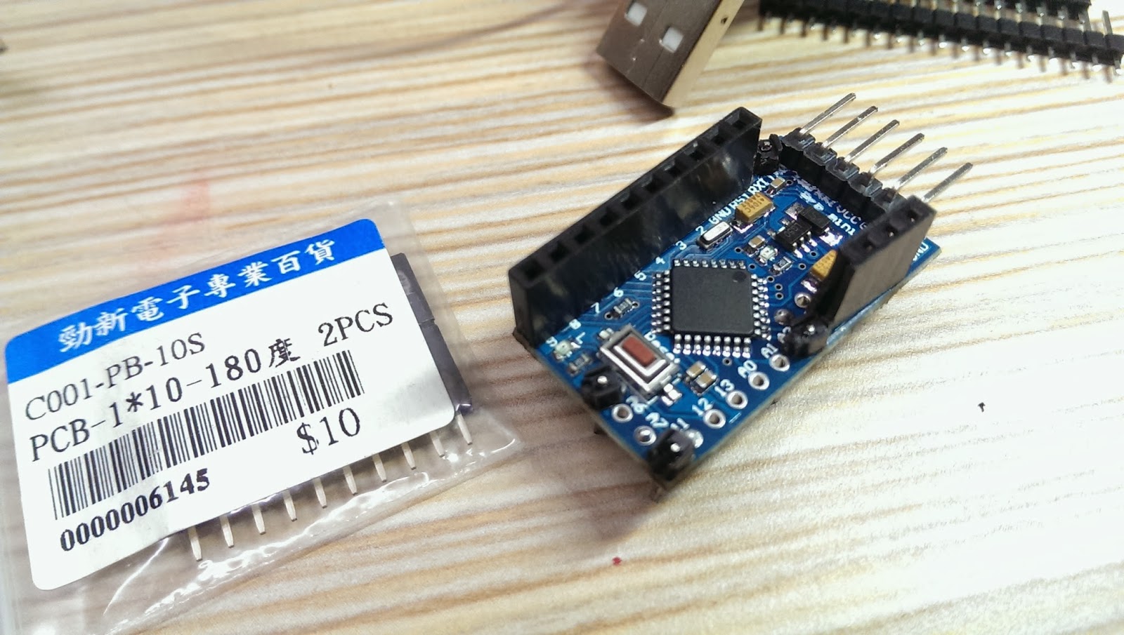
      Pick up the corner of the perfboard as the fix position. Then, solder pin header connectors on the side of Arduino mini pro, so we could have the flexibility to change wiring later.  Don't forget to face Arduino five data pins towards outside of the prefboard for easier connection to upload source code later.
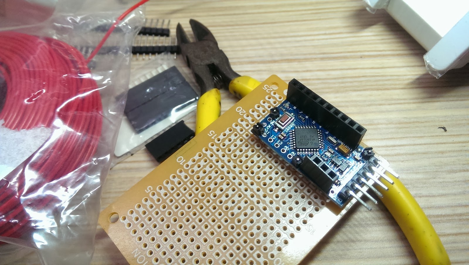
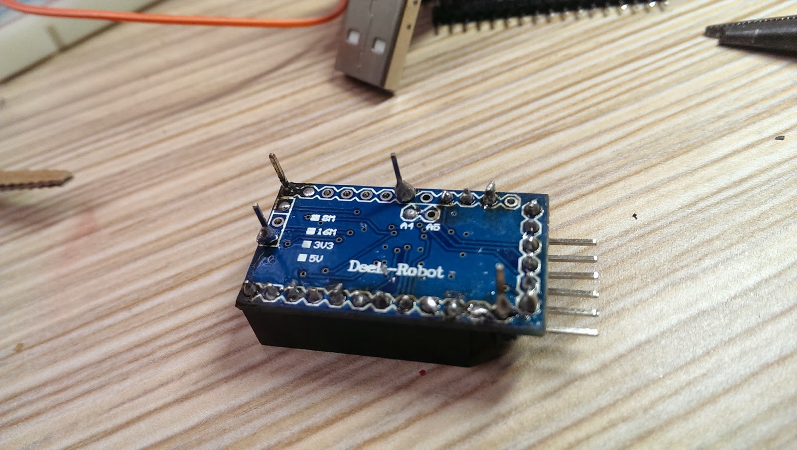
      Selected few unused solder holes from the Arduino Mini Pro and used the connection pin headers as supporting material on the perfboard. This could prevent unintentional shortage. See below:

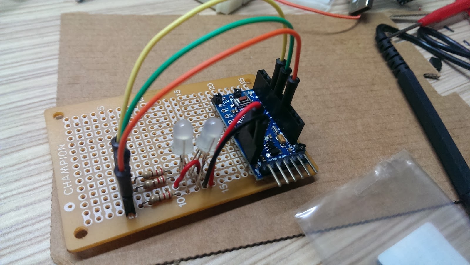
      After fixed Arduino Mini Pro in place, solder RGB LED, resistors, and wires to the prefboard. 
      Remember to power up to test the whole setup before moving forward.

      I used a screw to fix the relay module on the perfboard. However, fixed on one side is not stable enough, so I took a cable tight to keep the relay module tightly in place.  *Remember to reserve a very long IR reception wire*, so the IR receiver could placed outside of the celling light or the IR receiver might be obscured by the decorative glass cover.
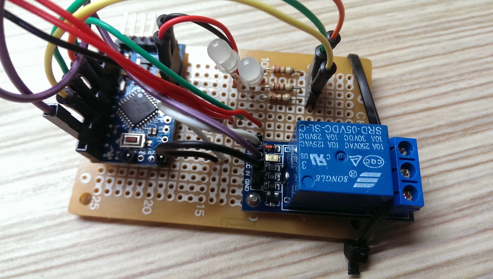


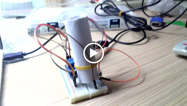
      Here is the over all system in action!


      Next, find a good power source for the system. 
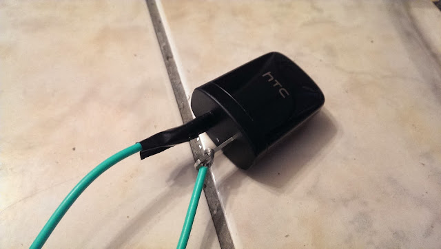
      For this project, I used a HTC smart phone charger. At least, HTC is (or was?) an international brand name smartphone company and has good reputation regarding to safety. Again, for safety reason, please use certified chargers only, such as CE, FCC, UL from well-know brand name company. *** Do not use no brand or very cheap chargers from unknown source. You are on your own risk! ***
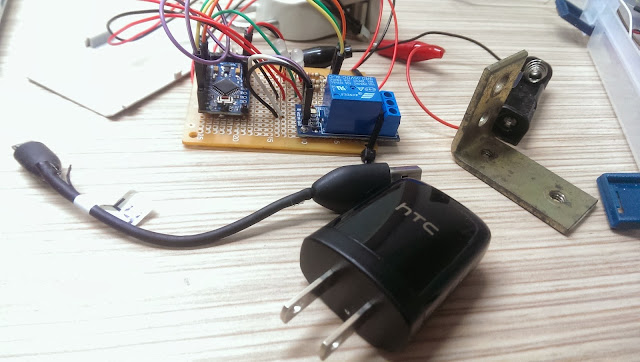


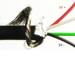
      I used a short USB cable to connect the HTC charger to the system.  Cut the USB cable near micro-B (smaller connector) and strip the shielding off the cable. In there, you will find four wires with GREEN, WHITE, RED, BLACK. Solder the RED(5V+) and BLACK(GND) wires to positive and negative respectively on the perfboard. 

      Cable connection:
      • USB type-A (Larger connector) to HTC charger
      • USB micro-B (smaller connector) to system


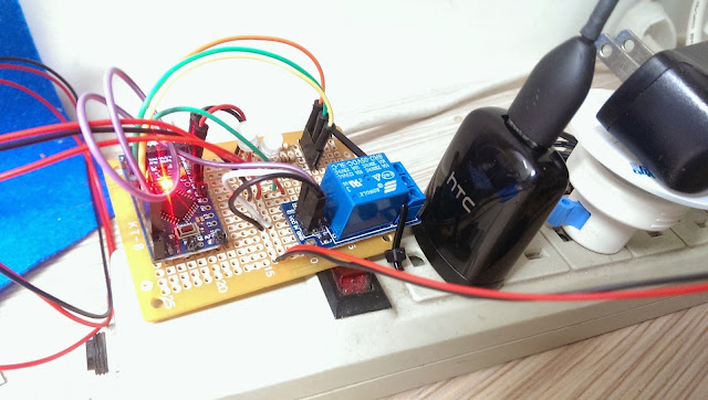
      After soldered the USB wires, plug the charger to power outlet and test the system.


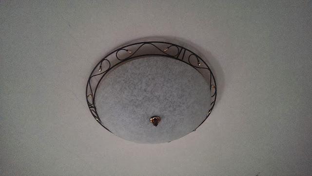
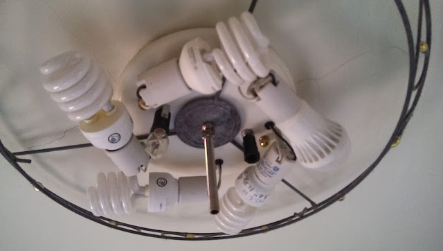
      My bedroom celling light looks like this below. It has a switch located at the entrance of the bedroom. And the switch works like this. After implement this system, the control of the switch will be shift to Arduino Mini Pro.

      For every switch on/off, it cycles through 

      1.  Turn on three lights
      2.  Turn off
      3.  Turn on Five lights
      4.  Turn off 
      5.  Turn on two lights
      6.  Turn off


      Carefully loosen the screw from the bottom glass cover and remove the decorative glass away.

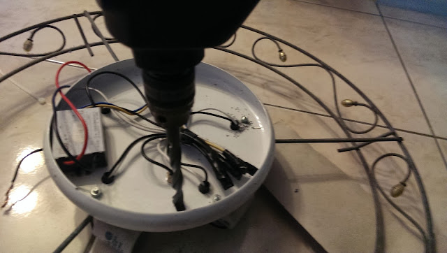
      Drill a hole on the light base for tightening the system.

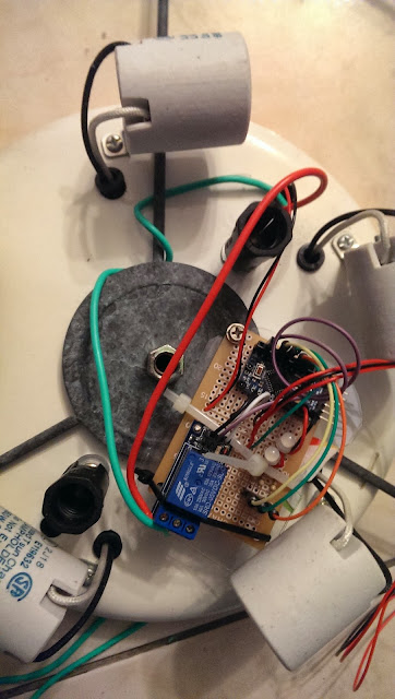
      Use a screw to secure the prefboard to the celling light as shown below.
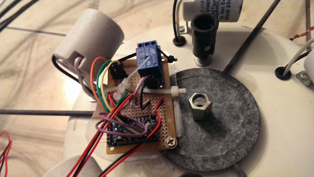

      *** Important: Wrong connection will cause the light not working ***
      • Connect 110v VCC to "Relay NO (Normally Open)" on the left
      • Connect Relay COM (Common connection) to 110v GND


      When connect AC 110V power line to phone charger, please make sure the isolation is done properly. It would be better to use Heat shrink tube for the isolation. However, I didn't have those on hand, so I used the isolation tape and tight them 3~4 times to ensure it's 100% isolated.  

      *** Disclaimer: Many experts expressed safety concerns for connecting Arduino with relay to AC 110V power!  I'm not responsible for any damage or lose that could happened to your projects or properties! You are at your own risk of doing this! ***


      Before tighten the light frame and decorative glass back to the celling, use the remote to test the system to see if it's working as expected.

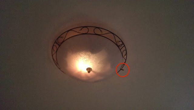
      See the red circle below, that's the IR receiver that I used an extended wire from the perfboard to the rim of the light to get better IR reception.


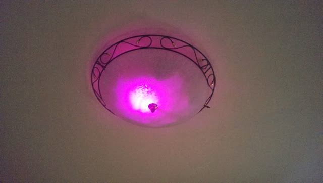
      Let's try to change the color with the TV remote.

      Finally, the project is completed! Watch the video below to see it in action!
      Now I can turn the celling light off directly from my bed after turn TV off!  


      This is the end of this tutorial. I hope you liked it! Please leave comments below and I will see you next time.

      Enjoy!


      2018/02/25

      Arduino - Switch celling light with TV remote (1/2)

       Preface

      It must be happened to you before that in a very cold night watching TV or movie in bed and you were ready for bed. You turned off the TV or DVD player with remote control easily. However, for the celling light, you just had to get out of the bed to turn the light off. What a pain! 

      After I searched the Internet, there are many examples out there suit for this purpose, such as IR receiver, relay module, and RGB LED shift hue and most of them have codes that I could utilize on this project.  

      Quick Link

      Material Needed

      • Arduino mini pro *1 
      • USB upload module *1 
      • Relay module (5V/10A/125V) * 1 
      • IR Receiver LED * 1 (Aixin AX-1838HS 38KHz * 1 / All 38KHz should work) 
      • RGB LED *2 
      • Resister 220 Om * 3
      • Few jump wires
      • Any TV or DVD remote you have at home
      • Breadboard * 1
      It's not difficult to find these components on Amazon or eBay.

      System Functionality

      Assign two buttons on the remote to control the celling light. Remember to assign less frequently used buttons on the remote or you might accidentally activate the particular function on your appliances. :)
      • Button 1: Turn on/off
      • Button 2: Switch LED color hues (static or color shifting)

      Schematic

      This schematic is made with Fritzing. 
      You can download it from its official website: www.fritzing.org


      Connections

      • IR Receiver to Arduino pin 2
      • IR Receiver + to VCC
      • IR Receiver - to GND
      • Relay + to VCC
      • Relay - to GND
      • Relay to Arduino pin 8
      • RGB Red to Resistor to Arduino pin 3
      • RGB Green to Resistor to Arduino pin 5
      • RGB Blue to Resistor to Arduino pin 6

      Check Remote IR code

      You have to find out the remote button IR codes on your remotes and embed them in the source code below for this project to work.


      For Example, my Sanyo TV remote has the following codes. As you can see, I have assigned two buttons for each feature to have a fall back plan.

      • Celling Light Switch function
        • Mute:irCode: 1CE318E7,  bits: 32  sanyoLight1
        • Channel minus :irCode: 1CE3D02F,  bits: 32  sanyoLight2
      • LED Switch function
        • Volume minus :irCode: 1CE3F00F,  bits: 32  sanyoLED1
        • CH View: irCode: 1CE352AD,  bits: 32 sanyoLED2

      To find out the IR codes for you remote, please refer to my previous IR Repeater Tutorial (Part 2)

      Source Code

      /*
       * Author: Stonez56
       * IRRemote for bedroom lighting control 
       *   Light buttons: Switch lights through the 
       *            cycle - 3, 5, 2, off with 2 types of remote
       *   LED buttons: Switch display random color a, b, transistion, off
       */
      
      #include <IRremote.h>
      
      // Setting up pins
      // Setup pin 8 for relay. 
      //    For some reason, Pin 13 will cause relay to switch one time
      //    when system powers on
      const int relay1Pin = 8; 
      const int redPin = 3;                    
      const int greenPin = 5;
      const int bluePin = 6;
      const int irReceiverPin = 2;
      
      // Milisecond to delay when shifting colors
      int colorShiftTime[] = {20, 10, 1, 50}; 
      int colorShiftTimeCounter = 0;
      
      int myPins[] = {2, 4, 8, 3, 6};
      int LEDstatus = 0;       // mode of LED or switch light
                          /*
                           * 0 = LED off
                           * 1 = LED orange
                           * 2 = LED color rotation
                           * 3 = Relay Light swtich
                           */
      
      int relay1Status = 0; // Switch of the relay; either 1 or 0;
      
      
      IRrecv irrecv(irReceiverPin);            
      decode_results results;  // IR decode_results 
      
      unsigned int rgbColour[3]; //RGB LED array
      
      unsigned int preCode = 0x0;  //Previous remote code
      unsigned int currentCode = 0x0; //Current remote code
      
      /* Define remote codes  
      Remote A (iBit Remote)
       Switch
        - (L/R) irCode: 609E09F6,  bits: 32 bitLigth1
        - Subtitle:irCode: 609E8877,  bits: 32  bitLight2
       LED Switch
        - Sound change irCode: 609E42BD,  bits: 32 bitLED1
        - Favorite channel:irCode: 609E728D,  bits: 32 bitLED2
        LED Color speed 
          - colorShiftTime: irCode: 
      
      */
       
      const unsigned long bitLight1 = 0x609E09F6;
      const unsigned long bitLight2 = 0x609E8877;
      const unsigned long bitLED1 = 0x609E42BD;
      const unsigned long bitLED2 = 0x609E728D; 
      const unsigned long bitLEDspeed = 0x609EAA55;
      /*
      Remote B (Sanyo Remote)
       Switch
        - Mute:irCode: 1CE318E7,  bits: 32  sanyoLight1
        - Channel minus :irCode: 1CE3D02F,  bits: 32  sanyoLight2
       LED Switch
        - Volume minus :irCode: 1CE3F00F,  bits: 32  sanyoLED1
        - CH View: irCode: 1CE352AD,  bits: 32 sanyoLED2
        LED Color speed
          - colorShiftTime: irCode: 
      
      */
      const unsigned long sanyoLight1 = 0x1CE318E7;
      const unsigned long sanyoLight2 = 0x1CE3F00F;
      const unsigned long sanyoLED1 = 0x1CE352AD;
      const unsigned long sanyoLED2 = 0x1CE3D02F;
      const unsigned long sanyoLEDspeed = 0x1CE350AF;
      
      void setup()
      {
        
        //////Serial.begin(9600);   
        irrecv.enableIRIn(); // enable IR pin
        pinMode(relay1Pin, OUTPUT);
        // Start off with the LED off.
        ledOff();
      }
      
      // Turn off LED
      void ledOff(){
        rgbColour[0] = 255;
        rgbColour[1] = 255;
        rgbColour[2] = 255;  
        setColourRgb(rgbColour[0], rgbColour[1], rgbColour[2]);
      
        preCode = currentCode;
        while(preCode == currentCode){
              currentCode = checkRemoteCode();
              // Check the code on Serial port
              Serial.print(rgbColour[0]); Serial.print(" | ");
              Serial.print(rgbColour[1]);  Serial.print(" | ");
              Serial.println(rgbColour[2]);
        }
      }
      
      /*
      * Turn on LED to Orange color
      */
      void ledOrange(){
        //LED color orange??
        rgbColour[0] = 65391;
        rgbColour[1] = 400;
        rgbColour[2] = 255;  
        setColourRgb(rgbColour[0], rgbColour[1], rgbColour[2]);
      
        preCode = currentCode;
        while(preCode == currentCode){
              currentCode = checkRemoteCode();
        }
      
      }
      
      
      /*
       * Rotating RGB LED color
       */
      void colorRotation(){
        // Start off with red.
        rgbColour[0] = 0;
        rgbColour[1] = 255;
        rgbColour[2] = 255;  
      
        preCode = currentCode;
       
        // Choose the colours to increment and decrement.
        for (int decColour = 0; decColour < 3; decColour += 1) {
          int incColour = decColour == 2 ? 0 : decColour + 1;
       
          // cross-fade the two colours.
          for(int i = 0; i < 255; i += 1) {
            rgbColour[decColour] -= 1;
            rgbColour[incColour] += 1;   
      
            setColourRgb(rgbColour[0], rgbColour[1], rgbColour[2]);
            delay(colorShiftTime[colorShiftTimeCounter]);
            currentCode = checkRemoteCode();
      
      /*
            Serial.print(" R:");Serial.print(rgbColour[0]);
            Serial.print(" G:");Serial.print(rgbColour[1]);
            Serial.print(" B: ");Serial.println(rgbColour[2]); 
            */     
            //if accepted new remote codes,
            //     exit this function and back to the main loop;
            if(preCode != currentCode){
              return;
            }
          }
        }
      } // End of LED color rotation
      
      
      /* This turn on/off relay switch
       *
       */
      void switchRelay(){
        relay1Status = 1 - relay1Status;   
         if(relay1Status == 0){
          digitalWrite(relay1Pin, HIGH);
          delay(500);
         }else{ 
          digitalWrite(relay1Pin, LOW);
          delay(500);
         }
      }
      
      /* Check remote code and return a mode to be changed
       *
       */
      int checkRemoteCode(){
        if (irrecv.decode(&results)) { // Received IR code and decoded ok!
          // Print to Serial port for debug purposes
          Serial.print("Color shift time: ");
          Serial.print(colorShiftTime[colorShiftTimeCounter]);
          Serial.print("  irCode: ");           
          Serial.print(results.value, HEX);    // IR decode
          Serial.print(",  bits: ");          
          Serial.println(results.bits);        // IR codes
          
          irrecv.resume();                    // Continue to receive next IR code 
          if(results.bits == 32){ //only 32bit code will be evaluated
            switch(results.value){
              /*All these buttons switch lights */ 
              case bitLight1:
              case bitLight2:
              case sanyoLight1:
              case sanyoLight2:  
              case 0x992A2843: //Benq Remote Green button for test
                   LEDstatus = 3; //switch relay;
      
                break;
              case bitLED1:
              case bitLED2:
              case sanyoLED1:
              case sanyoLED2:
                    //Check LEDstatus and switch to next mode
                    LEDstatus += 1;
                    if(LEDstatus >= 3){ 
                        LEDstatus = 0; //LEDstatus only has 0,1,2 if == 3, reset it to 0;
                    }
                break; 
              case bitLEDspeed:
              case sanyoLEDspeed:
                    colorShiftTimeCounter++;
                    if(colorShiftTimeCounter==4){ 
                        colorShiftTimeCounter=1; //only 4 elements, from 0~3
                      }
                    colorShiftTime[colorShiftTimeCounter];
                break;
              default:
                break;        
            } //switch
          } // check 32bits
        } //end of get a remote code
      
        return LEDstatus;
      }
      
      void setColourRgb(unsigned int red, unsigned int green, unsigned int blue) {
        analogWrite(redPin, red);
        analogWrite(greenPin, green);
        analogWrite(bluePin, blue);
       }
      
      void loop(){
        switch(LEDstatus){
           case 0:
              ledOff();
              break;
           case 1:
              ledOrange();
              break;
           case 2:
              colorRotation();
              break;
           case 3:
              switchRelay();
              LEDstatus = 99;
              break;
           default: // set it up to do nothing, but wait the remote code to activate
               break;
        }
        //constanly check new remote code
        LEDstatus = checkRemoteCode();
        //////Serial.print("LEDstatus: ");Serial.println(LEDstatus);
      } // end of loop
      
      
      Here is the prototype in the photo below.


      In next tutorial, I will show you the 2nd phase to put everything together and install the whole system in the celling light.  See you soon!


      2014/01/19

      Arduino 專案 - 以電視遙控器控臥室天花板電燈開關 (2) : Arduino Project - Switch Bedroom Light with TV remote Part 2

      上次完成 Arduino 用TV搖控器來開關燈 開發原型後,一直到今天才把它完全的做在一個麵包板上。由於是電子相關的新手,真是花了很多功夫才完成。在過程中,我還把正負極裝反,害我以為 Arduino mini pro 被我燒毀了! 找了好久,還好我有發現這個問題,不然,你也看不到這個例子了!

      After I completed Remote control light switch with Arduino and TV remote project last time, I was looking for ways to move all components on to a perfboard and ready for a permanent setup. Due to I am really new to electronics, it took me a lot of time to get the job done. During the process, I accidentally soldered the power source positive to negative and negative to positive. I was panic and, for once, I thought I had burned the Arduino mini pro.  I was happy that I found the problem and solved it after few hours...


      對沒學過焊接的新手,把零件焊到電路板上,真的是很不容易!! 看我焊的跟狗啃的沒兩樣。
      For a newbie like me whom never learn how to solder, soldering components to the perfboard is really challenging!

      我到電子零件店買了這個編號 KT-8 的電路板。
      使用長的接腳,拿它來當固定 Arduino mini pro 的工具。
      I bought this perfboard coded "KT-8" in an electronic component shop and it only cost NT$10.
      With the long connection pins, I utilized them to fix Arduino mini pro in place on the perfboard.

      一開始先選定這個角落當作 Arduino mini pro 固定位置,要記得把五個 pin 腳朝外,這樣要上傳程式比較方便。
      Pick up the corner of the KT-8 perfboard as the fix position. Don't forget to face the five pins towards outside of the KD-8 for easier connection to the USB uploader later.


      我不想一開始就把 Arduino mini pro 的腳位焊死,這樣我可以較彈性的應用,所以也買了底下這樣的接口,所以我可以任意調動我要用的 pin 。我只有把大概用的到的腳位加上接口,其它的就留著作為固定的用途。

      I picked up the connection pins as shown below to solder them on the side of Arduino mini pro, so I could have the flexibility to change connection to the pins later in the project.  As you can see, I saved couple of empty spots on the Arduino mini pro, so I could use them to fix it to the perfboard later.


      找四個留下的空 pin 腳,焊上排針來支撐 Arduino mini pro。我把排針剪下一支一支的共四支,等一會再把這四個排針焊到麵包板上。

      Decided four empty spots and used the connection headers came with Arduino mini pro and soldered them together. Later, these connection headers would become the supporting material on the perfboard for Arduino mini pro. The connection headers are in a row of 20, so I cut down a single header totaling 4 of them and make them into supporting materials.


      Photo above:  Long connection pins for fixing Arduino mini pro in place on the perfboard.

      我的工作桌...
      My soldering table...


      固定 Arduino mini pro 後,焊上 LED,電阻,再接上線路,記得先測試一下。
      我在這裡測試時,發現它不會動,花了好久時間才發現是正負接反了!
      After fixed Arduino mini pro in position, solder RGB LED, resistors, and wires. 
      Remember to test the whole setup before move forward. 


      Photos of soldering work here:

      因為繼電器模組上有一個洞,所以我先用電鑽在電路板挖個洞,再用螺絲把它鎖住。
      但固定單邊不夠勞固,所以我又用一條束帶把繼電器模組緊緊的繫在電路板上。
      Drilled a hole on the perfboard, and took a screw to fix the relay module on the perfboard. However, fixed on one side is not enough, so I took a cable tight to keep the relay module tightly on the perfboard.


      Photos of entire board here:

      我刻意把紅外線接收器的線做長一點,想說把它延伸到天花板燈的外緣,這樣遙控訊號才不會被我燈上的裝飾玻璃給擋住。結果測試後發現這根本不需要,因為紅外線接收訊號功能很強,我試著隔著 Macbook Air 的螢幕,居然還可以接收的到!

      I intended to make the IR receiver wire extra longer, so I could extend the IR receiver outside the bed room light or it might be obscured by the decorative glasses. After few tests, I found out the IR receiver could even receive the TV remote signal even I intended put it behind my Macbook Air display!

      看一下這兩周以來的成果如下,接下來要為它接上電源及安裝到天花板上,才算真正的完成。
      After two weeks of hard working, here is the project I had so far. Next time, I will need to find a 5V power source for the perfboard and think how to place it into bed room light.

      Video of the working project on perfboard.


      2014/01/14

      Arduino 專案 - 以電視遙控器控臥室天花板電燈開關 (1) - Arduino Project - Switch Ceiling Light with TV remote Part 1

      這一兩個月來,一直在看 Arduino 的相關資料,終於有一個 "勘用" 的東西...
      It's been a month a or two that I have been studying Arduino related information.
      Finally, I came up with a useful cases for a project that could potentially solve my pain point.

      睡覺前,在寒冷的冬天,要從床上起關燈時,總覺得很麻煩...
      所以當初看到 Arduino, 第一個想完成的 project 就是,利用電視遙控器來控制天花板上的燈了...上網找了一下資料,沒想到已有很多前輩已經有寫類似的,所以就參考來用了!這是我做初版,coding 太久沒寫了,所以很亂,還好能運作...
      It must be happened to you before that in a very cold night watching TV or movie in bed and you were ready for bed. You turned off the TV or DVD player with remote control easily. However, for the bedroom light, you just had to get out of the bed to turn the light off. What a pain point!!

      So, my first project is called "Remote control light switch with Arduino and TV remote".  After I searched the internet, there are many examples already out there, such as IR receiver, relay module, RGB LED shift hue and most of them have codes that I could utilize on my project.  It's been a long time since my last coding, so the code is kind of messy, but it worked!


      零件清單(全部在台灣拍賣上取得: Components used list (All acquired on auction sites) 
      Arduino mini pro * 1 = NT$125

      Arduino USB 上傳模組 
      (Arduino USB upload module) *1 = NT$140 
      5V / 10A 125V 繼電器模組 (Relay module) * 1 = NT$65
      IR 接收器 (IR Receiver) * 1 = $4
      RGB LED *2 = $6
      一些線材 (Some wires) $10
      家裡電視 or DVD遙控器 (TV or DVD remote) Free

      麵包板 (Breadboard ) * 1
      創作過程樂趣 (Effort and enjoyment of this creativity, priceless) * 1 無價! 

      模組搖控功能如下:(Remote module Function)

      Assign two button on your TV or DVD remote to control:

      Button 1: A) LED 小燈亮
      橘色 (取代原本小夜燈), B) LED 彩色循環,C) LED Off 
      _________ Switch among A) LED bed room night light B) Shift RGB LED colour hues C) LED offButton 2: 切換繼電器開關 (以後把110V燈接上去,就可以開關了)
      ________ Turn light switch (I have to plug 110V power plug on the relay later)

      設定的 Button 要是最不常用的,最好是電視關掉時,按下去的鈕不會有任何反應。像電源鈕就不建議,以免使用時關燈時又把電視打開.... 那就很 Orz..
      You can share the TV remote for this project, so there is no need to use a separate remote. Make sure the buttons you are going to use are less frequently used on the remotes. Power buttons on the remote are not recommended, since it's likely that you turn off the light, but the TV or DVD is turned on. I assume that's not something you would like to see.
      模組線路圖:(My first drawing of the wiring chart)

      原型電路板 +電視遙控器:
      Here is prototype + TV remote used for the project

      小燈 +LED 彩色循環 +繼電器關關。注意聽,影片中有切換繼電器的聲音。
      Bed room night light -> Shift LED colour hue -> LED off
      Relay on / off (Listen carefully, you can hear the relay switch in the video)


      PS:你可以多設幾支搖控器,以免要用的那支沒在床邊,還是得起床!像我設了兩支臥室常用的。
      PS:  You may setup few more remote for the same function. Just in case, the light remote is not with you and then you need to get out of the bed eventually. In  my project, I have setup 2 most frequently used remote in the bed room.

      接下來: 我要想想如何才能裝到天花板的電燈裡!
      What's next, I need to figure out how to connect this module to the light on the celling.