This is the part two of Switch celling light with TV remote tutorial. If needed, please check out the part one from link below. By the way, the source code is also available there.
Quick Link
- Tutorial Part 1: Switch celling light with TV remote (1/2)
- To find out the IR codes for you remote, check this tutorial: IR Repeater Tutorial (Part 2)
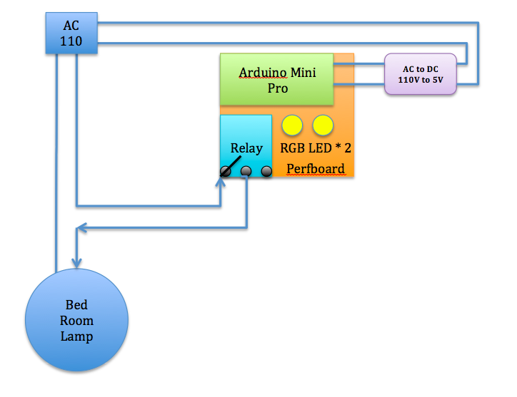
System Design
See the illustration below. I used a phone charger(purple block; AC110V to DC5V) to supply power from 110v AC power outlet from the celling. The Arduino controls the relay module to switch the celling light and Arduino interpret IR code to change RGB LED to shift color and on/off accordingly.
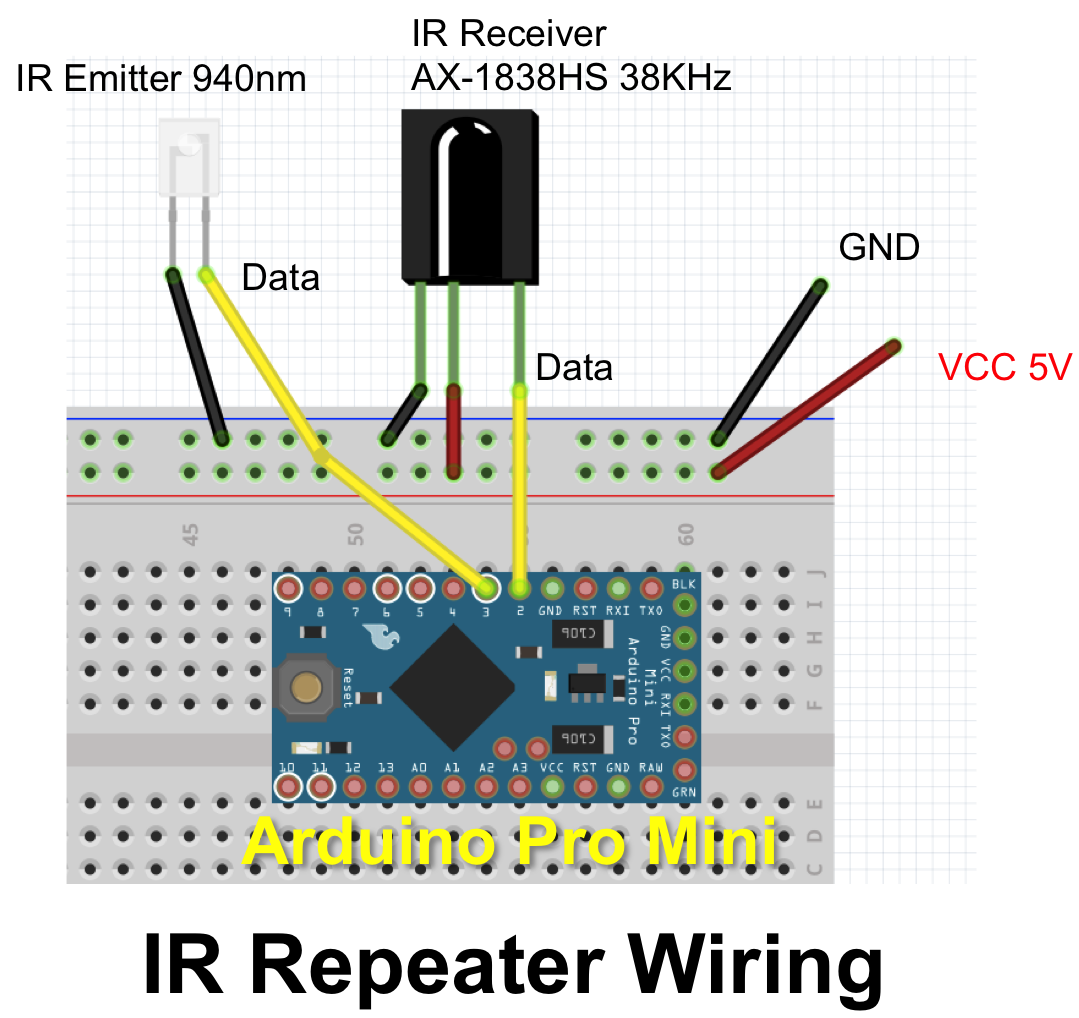
Connections
- IR Receiver to Arduino pin 2
- IR Receiver + to VCC
- IR Receiver - to GND
- Relay + to VCC
- Relay - to GND
- Relay to Arduino pin 8
- RGB Red to Resistor to Arduino pin 3
- RGB Green to Resistor to Arduino pin 5
- RGB Blue to Resistor to Arduino pin 6
- *** CAUTION: Turn off home main power switch first before 110V connection! ***
- *** Connect 110V to the system after you secure prefboard to the celling light ***
- Connect 110V VCC to "Relay NO (Normally Open)" on the left
- Connect Relay COM (Common connection) to 110V GND.
Step by step
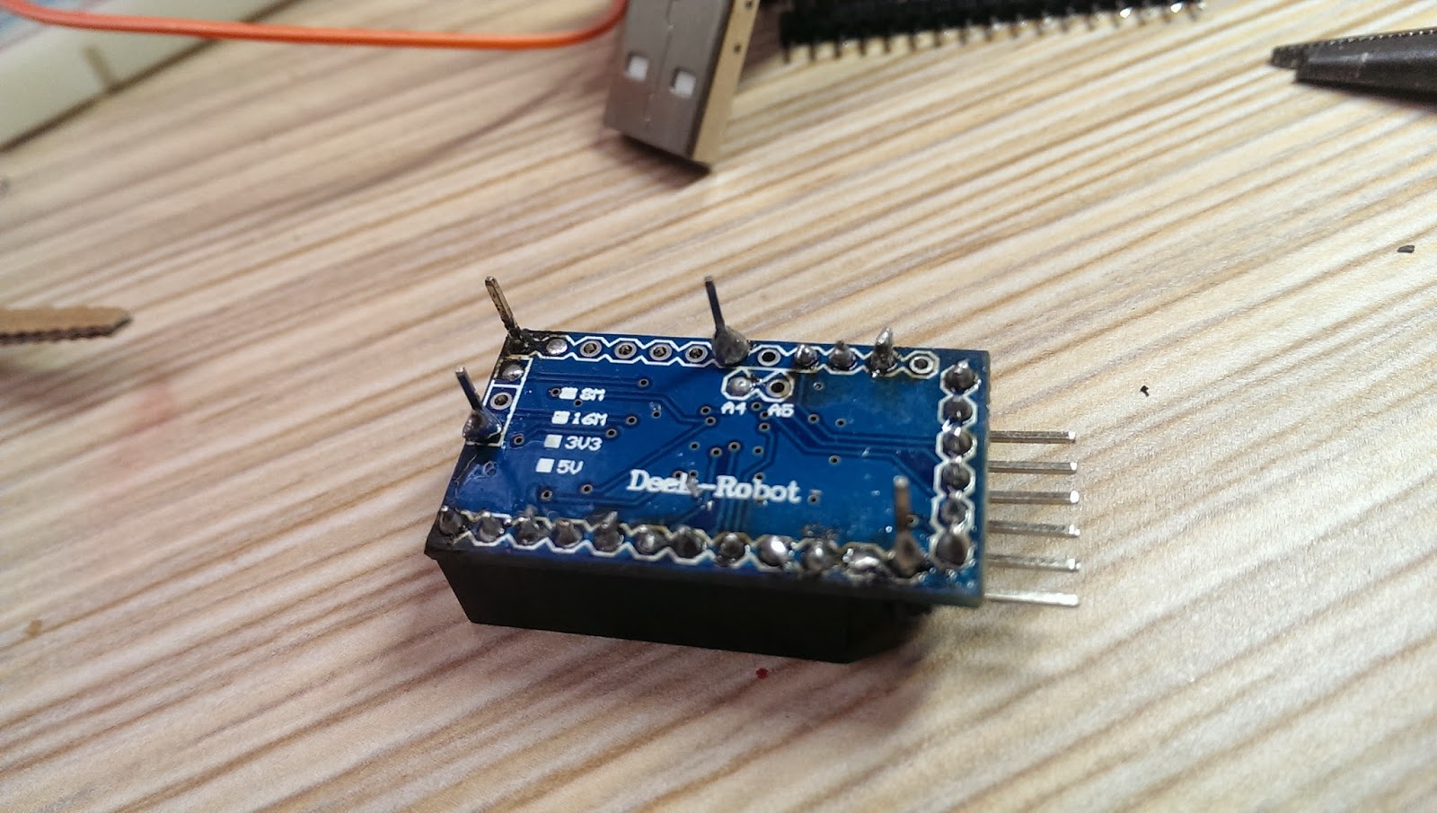
Solder pins to Arduino mini pro.
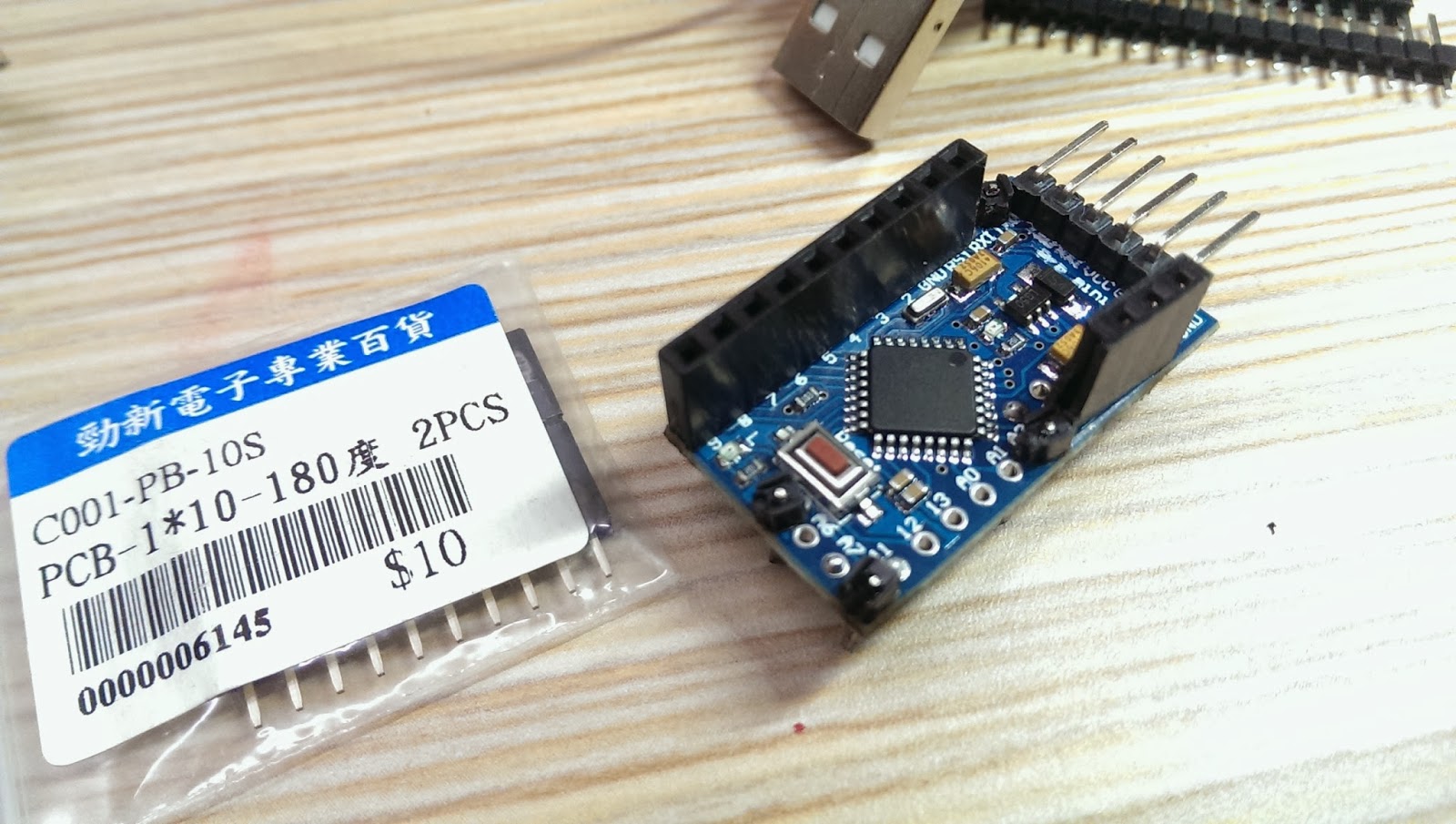
Pick up the corner of the perfboard as the fix position. Then, solder pin header connectors on the side of Arduino mini pro, so we could have the flexibility to change wiring later. Don't forget to face Arduino five data pins towards outside of the prefboard for easier connection to upload source code later.
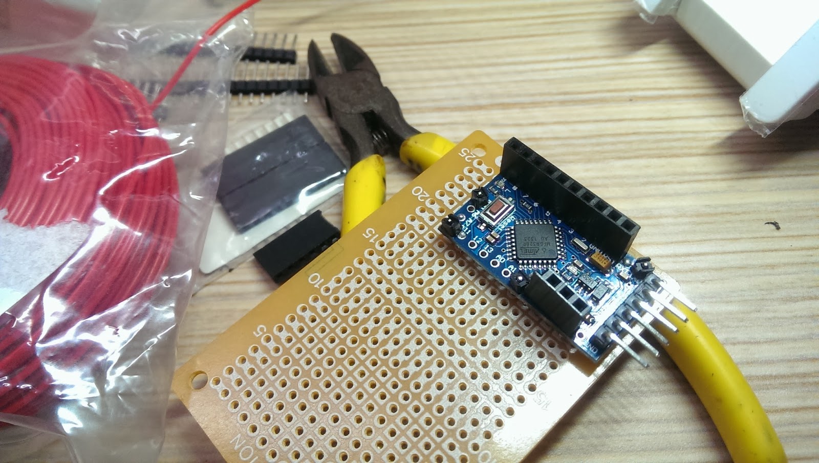
Selected few unused solder holes from the Arduino Mini Pro and used the connection pin headers as supporting material on the perfboard. This could prevent unintentional shortage. See below:
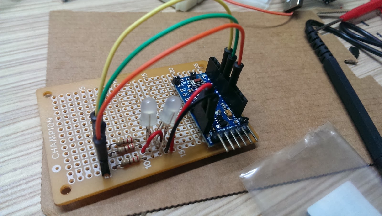
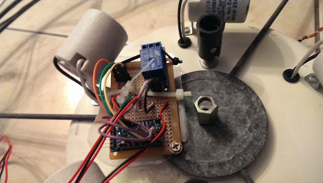
After fixed Arduino Mini Pro in place, solder RGB LED, resistors, and wires to the prefboard.
Remember to power up to test the whole setup before moving forward.
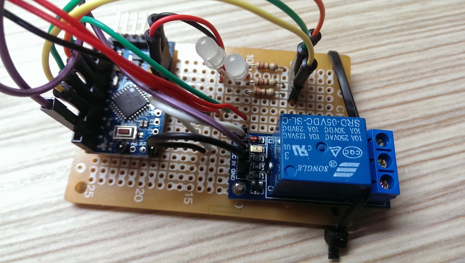
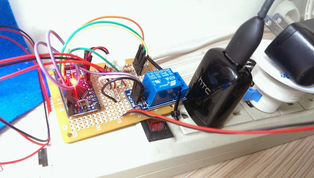
I used a screw to fix the relay module on the perfboard. However, fixed on one side is not stable enough, so I took a cable tight to keep the relay module tightly in place. *Remember to reserve a very long IR reception wire*, so the IR receiver could placed outside of the celling light or the IR receiver might be obscured by the decorative glass cover.
Here is the over all system in action!
Next, find a good power source for the system.
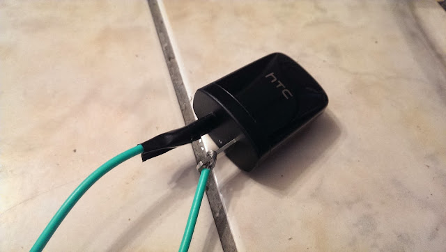
For this project, I used a HTC smart phone charger. At least, HTC is (or was?) an international brand name smartphone company and has good reputation regarding to safety. Again, for safety reason, please use certified chargers only, such as CE, FCC, UL from well-know brand name company. *** Do not use no brand or very cheap chargers from unknown source. You are on your own risk! ***
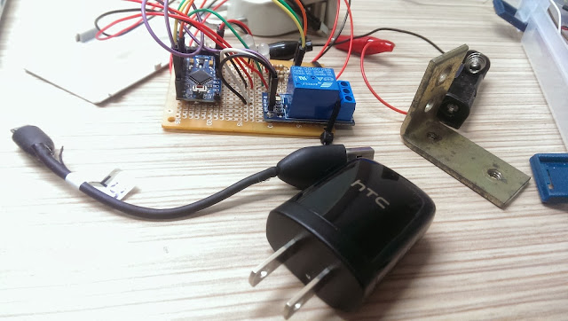
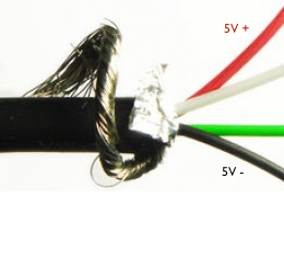
I used a short USB cable to connect the HTC charger to the system. Cut the USB cable near micro-B (smaller connector) and strip the shielding off the cable. In there, you will find four wires with GREEN, WHITE, RED, BLACK. Solder the RED(5V+) and BLACK(GND) wires to positive and negative respectively on the perfboard.
Cable connection:
- USB type-A (Larger connector) to HTC charger
- USB micro-B (smaller connector) to system
After soldered the USB wires, plug the charger to power outlet and test the system.
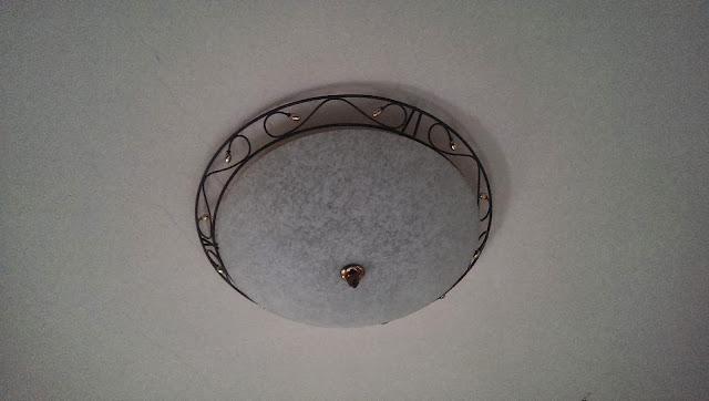
My bedroom celling light looks like this below. It has a switch located at the entrance of the bedroom. And the switch works like this. After implement this system, the control of the switch will be shift to Arduino Mini Pro.
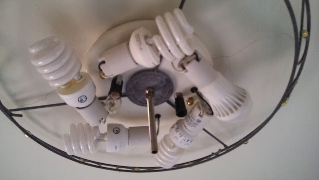
For every switch on/off, it cycles through
For every switch on/off, it cycles through
- Turn on three lights
- Turn off
- Turn on Five lights
- Turn off
- Turn on two lights
- Turn off
Carefully loosen the screw from the bottom glass cover and remove the decorative glass away.
Drill a hole on the light base for tightening the system.
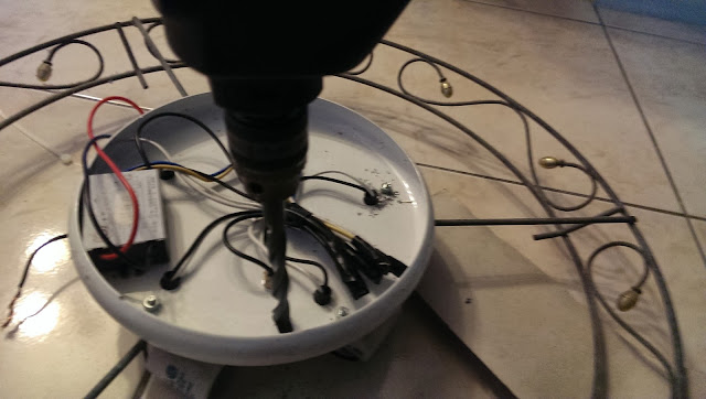
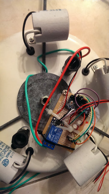
Use a screw to secure the prefboard to the celling light as shown below.
*** Important: Wrong connection will cause the light not working ***
- Connect 110v VCC to "Relay NO (Normally Open)" on the left
- Connect Relay COM (Common connection) to 110v GND.
When connect AC 110V power line to phone charger, please make sure the isolation is done properly. It would be better to use Heat shrink tube for the isolation. However, I didn't have those on hand, so I used the isolation tape and tight them 3~4 times to ensure it's 100% isolated.
*** Disclaimer: Many experts expressed safety concerns for connecting Arduino with relay to AC 110V power! I'm not responsible for any damage or lose that could happened to your projects or properties! You are at your own risk of doing this! ***
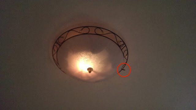
Before tighten the light frame and decorative glass back to the celling, use the remote to test the system to see if it's working as expected.
See the red circle below, that's the IR receiver that I used an extended wire from the perfboard to the rim of the light to get better IR reception.
Let's try to change the color with the TV remote.
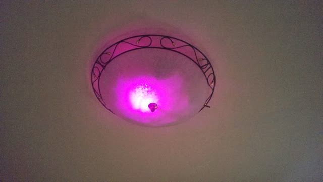
Finally, the project is completed! Watch the video below to see it in action!
Now I can turn the celling light off directly from my bed after turn TV off!
This is the end of this tutorial. I hope you liked it! Please leave comments below and I will see you next time.
Enjoy!