In September 2014, I created this project with Arduino Mini Pro Mini and Android APP loved by so many readers! There are more than 100,000 App downloads by now! Since then, quite of few readers asked me how to change the sketch to be used on ESP32 with built-in Bluetooth. Here it is!! 😀
Be aware that LED PWM pins used on ESP32 were completely different, since Arduino Mini Pro and ESP32 have different architectures.
For ESP32, I used following pins:
Pin 13 = Red
Pin 12 = Green
Pin 14 = Blue
Caution: ESP32 does not allow to use pin 6, 7, 8, 9, 10, 11 or it will crash and reboot. I tried...😂
Also, there is no analogWrite() function in ESP32, so I need to change analogWrite() to ledcWrite() with
This is the part two of Switch celling light with TV remote tutorial. If needed, please check out the part one from link below. By the way, the source code is also available there.
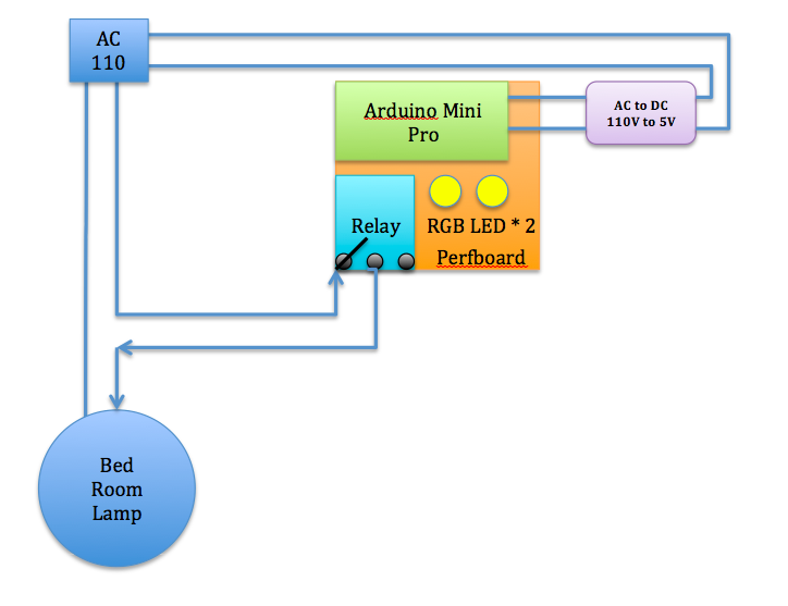
See the illustration below. I used a phone charger(purple block; AC110V to DC5V) to supply power from 110v AC power outlet from the celling. The Arduino controls the relay module to switch the celling light and Arduino interpret IR code to change RGB LED to shift color and on/off accordingly.
Connections
IR Receiver to Arduino pin 2
IR Receiver + to VCC
IR Receiver - to GND
Relay + to VCC
Relay - to GND
Relay to Arduino pin 8
RGB Red to Resistor to Arduino pin 3
RGB Green to Resistor to Arduino pin 5
RGB Blue to Resistor to Arduino pin 6
*** CAUTION: Turn off home main power switch first before 110V connection! ***
*** Connect 110V to the system after you secure prefboard to the celling light ***
Connect 110V VCC to "Relay NO (Normally Open)" on the left
Connect Relay COM (Common connection) to 110V GND.
Step by step
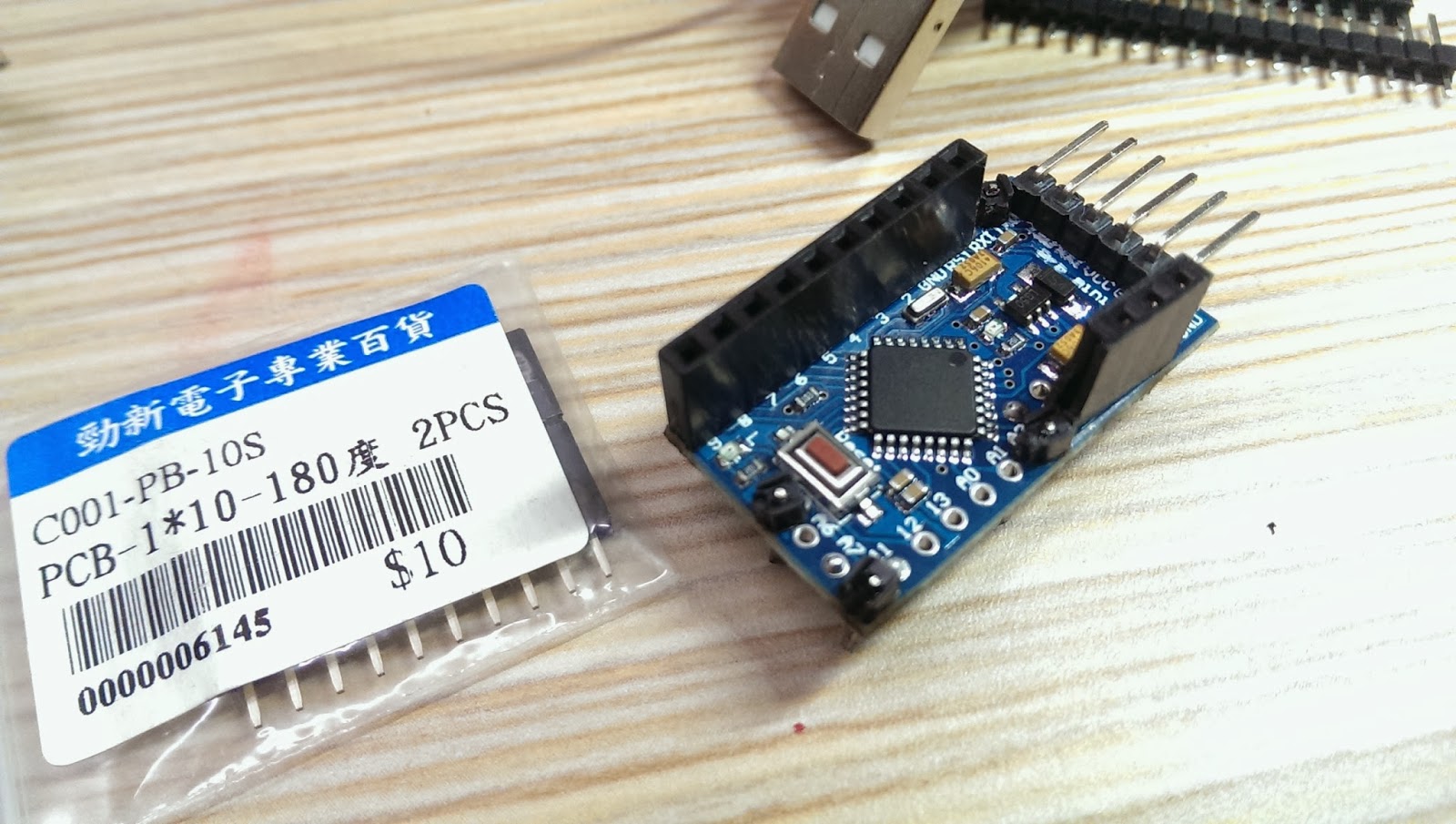
Solder pins to Arduino mini pro.
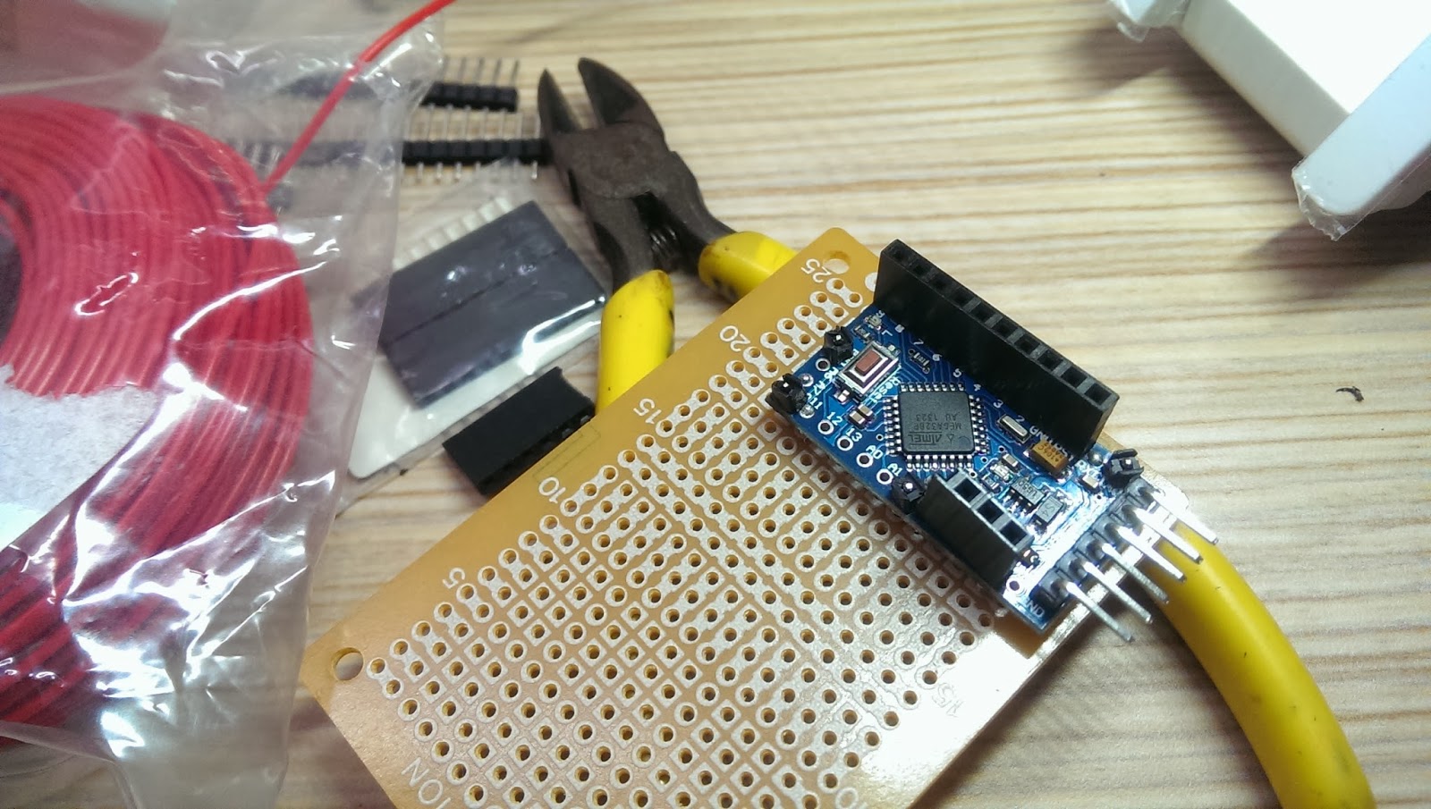
Pick up the corner of the perfboard as the fix position. Then, solder pin header connectors on the side of Arduino mini pro, so we could have the flexibility to change wiring later. Don't forget to face Arduino five data pins towards outside of the prefboard for easier connection to upload source code later.
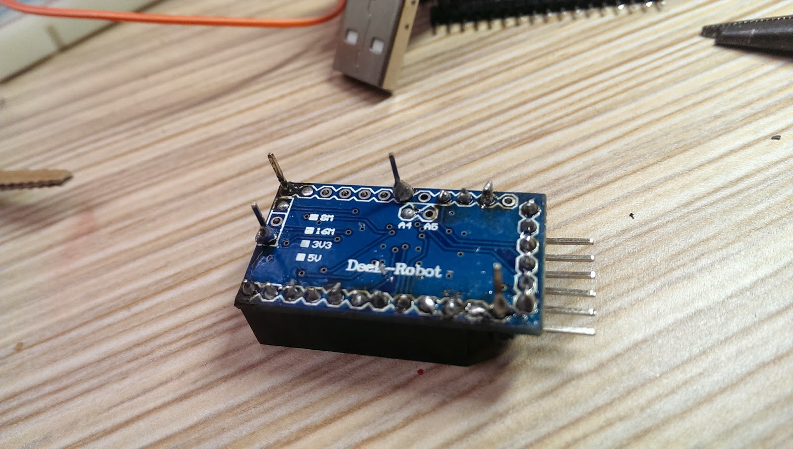
Selected few unused solder holes from the Arduino Mini Pro and used the connection pin headers as supporting material on the perfboard. This could prevent unintentional shortage. See below:
After fixed Arduino Mini Pro in place, solder RGB LED, resistors, and wires to the prefboard.
Remember to power up to test the whole setup before moving forward.
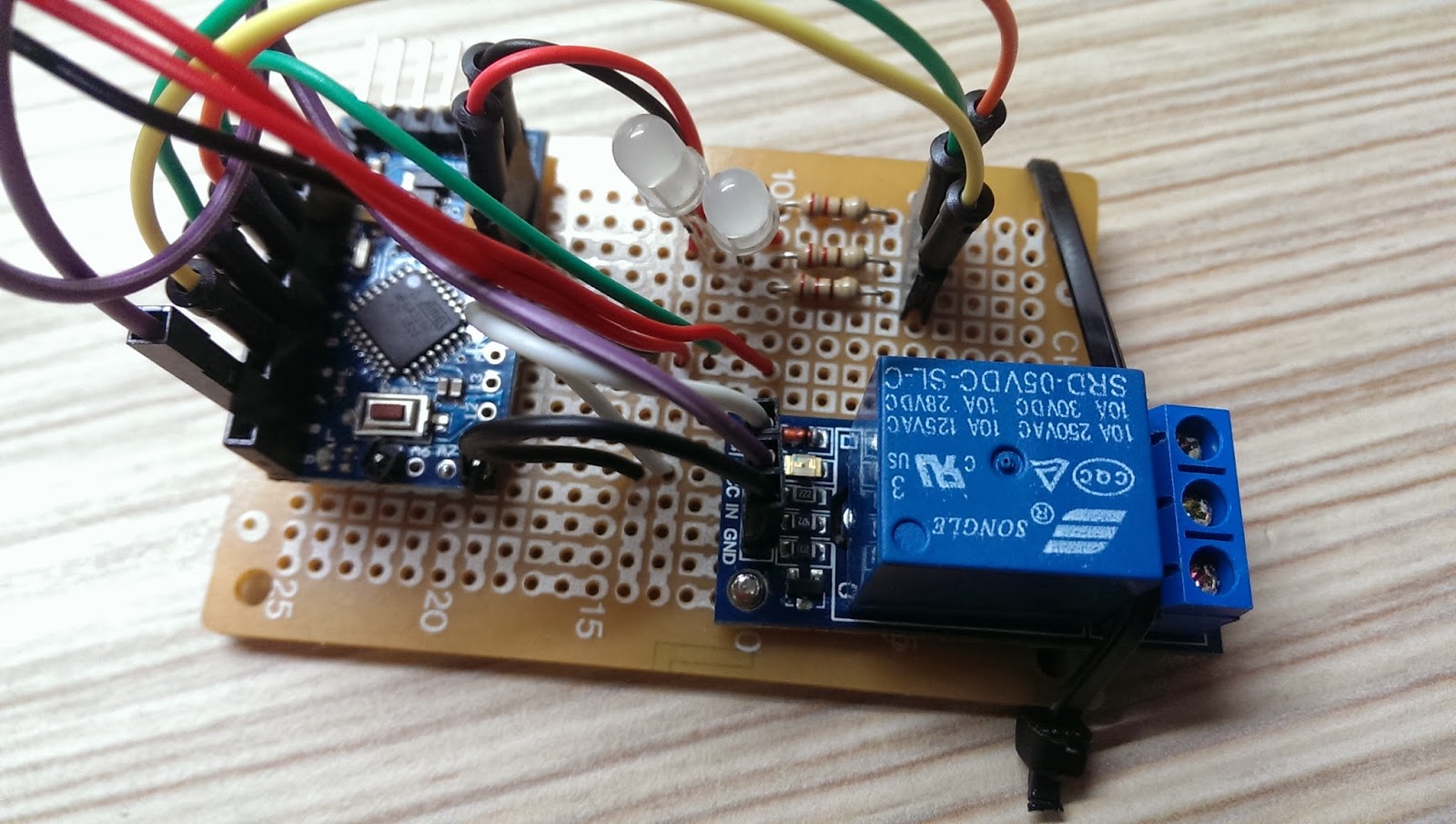
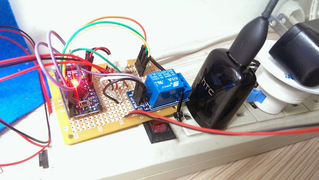
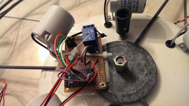
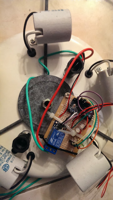
I used a screw to fix the relay module on the perfboard. However, fixed on one side is not stable enough, so I took a cable tight to keep the relay module tightly in place. *Remember to reserve a very long IR reception wire*, so the IR receiver could placed outside of the celling light or the IR receiver might be obscured by the decorative glass cover.
Here is the over all system in action!
Next, find a good power source for the system.
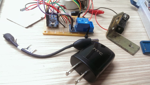
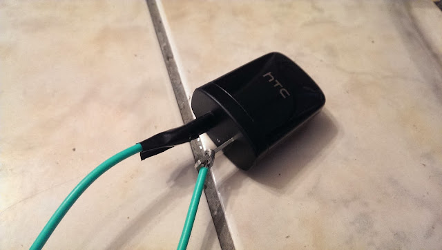
For this project, I used a HTC smart phone charger. At least, HTC is (or was?) an international brand name smartphone company and has good reputation regarding to safety. Again, for safety reason, please use certified chargers only, such as CE, FCC, UL from well-know brand name company. *** Do not use no brand or very cheap chargers from unknown source. You are on your own risk! ***
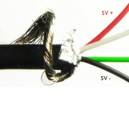
I used a short USB cable to connect the HTC charger to the system. Cut the USB cable near micro-B (smaller connector) and strip the shielding off the cable. In there, you will find four wires with GREEN, WHITE, RED, BLACK. Solder the RED(5V+) and BLACK(GND) wires to positive and negative respectively on the perfboard.
Cable connection:
USB type-A (Larger connector) to HTC charger
USB micro-B (smaller connector) to system
After soldered the USB wires, plug the charger to power outlet and test the system.
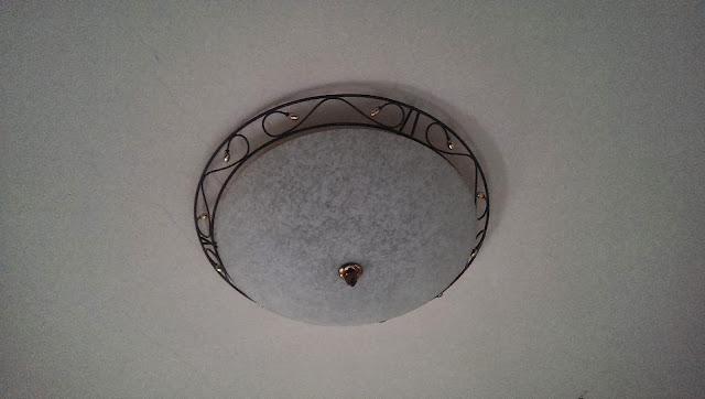
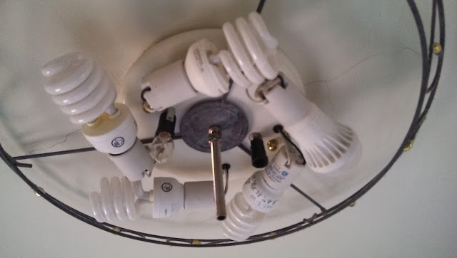
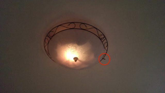
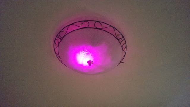
My bedroom celling light looks like this below. It has a switch located at the entrance of the bedroom. And the switch works like this. After implement this system, the control of the switch will be shift to Arduino Mini Pro.
For every switch on/off, it cycles through
Turn on three lights
Turn off
Turn on Five lights
Turn off
Turn on two lights
Turn off
Carefully loosen the screw from the bottom glass cover and remove the decorative glass away.
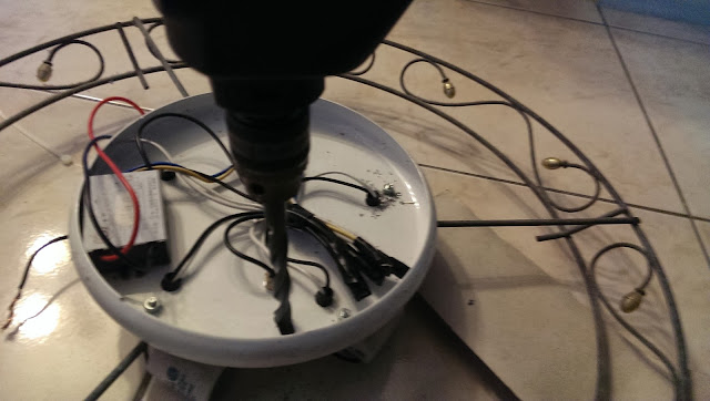
Drill a hole on the light base for tightening the system.
Use a screw to secure the prefboard to the celling light as shown below.
*** Important: Wrong connection will cause the light not working ***
Connect 110v VCC to "Relay NO (Normally Open)" on the left
Connect Relay COM (Common connection) to 110v GND.
When connect AC 110V power line to phone charger, please make sure the isolation is done properly. It would be better to use Heat shrink tube for the isolation. However, I didn't have those on hand, so I used the isolation tape and tight them 3~4 times to ensure it's 100% isolated.
*** Disclaimer: Many experts expressed safety concerns for connecting Arduino with relay to AC 110V power! I'm not responsible for any damage or lose that could happened to your projects or properties! You are at your own risk of doing this! ***
Before tighten the light frame and decorative glass back to the celling, use the remote to test the system to see if it's working as expected.
See the red circle below, that's the IR receiver that I used an extended wire from the perfboard to the rim of the light to get better IR reception.
Let's try to change the color with the TV remote.
Finally, the project is completed! Watch the video below to see it in action!
Now I can turn the celling light off directly from my bed after turn TV off!
This is the end of this tutorial. I hope you liked it! Please leave comments below and I will see you next time.
It must be happened to you before that in a very cold night watching TV or movie in bed and you were ready for bed. You turned off the TV or DVD player with remote control easily. However, for the celling light, you just had to get out of the bed to turn the light off. What a pain!
After I searched the Internet, there are many examples out there suit for this purpose, such as IR receiver, relay module, and RGB LED shift hue and most of them have codes that I could utilize on this project.
IR Receiver LED * 1 (Aixin AX-1838HS 38KHz * 1 / All 38KHz should work)
RGB LED *2
Resister 220 Om * 3
Few jump wires
Any TV or DVD remote you have at home
Breadboard * 1
It's not difficult to find these components on Amazon or eBay.
System Functionality
Assign two buttons on the remote to control the celling light. Remember to assign less frequently used buttons on the remote or you might accidentally activate the particular function on your appliances. :)
Button 1: Turn on/off
Button 2: Switch LED color hues (static or color shifting)
/*
 * Author: Stonez56
 * IRRemote for bedroom lighting control
 *   Light buttons: Switch lights through the
 *            cycle - 3, 5, 2, off with 2 types of remote
 *   LED buttons: Switch display random color a, b, transistion, off
 */

#include <IRremote.h>

// Setting up pins
// Setup pin 8 for relay.
//    For some reason, Pin 13 will cause relay to switch one time
//    when system powers on
const int relay1Pin = 8;
const int redPin = 3;
const int greenPin = 5;
const int bluePin = 6;
const int irReceiverPin = 2;

// Milisecond to delay when shifting colors
int colorShiftTime[] = {20, 10, 1, 50};
int colorShiftTimeCounter = 0;

int myPins[] = {2, 4, 8, 3, 6};
int LEDstatus = 0;       // mode of LED or switch light
                    /*
                     * 0 = LED off
                     * 1 = LED orange
                     * 2 = LED color rotation
                     * 3 = Relay Light swtich
                     */

int relay1Status = 0; // Switch of the relay; either 1 or 0;


IRrecv irrecv(irReceiverPin);
decode_results results;  // IR decode_results

unsigned int rgbColour[3]; //RGB LED array

unsigned int preCode = 0x0;  //Previous remote code
unsigned int currentCode = 0x0; //Current remote code

/* Define remote codes
Remote A (iBit Remote)
 Switch
  - (L/R) irCode: 609E09F6,  bits: 32 bitLigth1
  - Subtitle:irCode: 609E8877,  bits: 32  bitLight2
 LED Switch
  - Sound change irCode: 609E42BD,  bits: 32 bitLED1
  - Favorite channel:irCode: 609E728D,  bits: 32 bitLED2
  LED Color speed
    - colorShiftTime: irCode:

*/

const unsigned long bitLight1 = 0x609E09F6;
const unsigned long bitLight2 = 0x609E8877;
const unsigned long bitLED1 = 0x609E42BD;
const unsigned long bitLED2 = 0x609E728D;
const unsigned long bitLEDspeed = 0x609EAA55;
/*
Remote B (Sanyo Remote)
 Switch
  - Mute:irCode: 1CE318E7,  bits: 32  sanyoLight1
  - Channel minus :irCode: 1CE3D02F,  bits: 32  sanyoLight2
 LED Switch
  - Volume minus :irCode: 1CE3F00F,  bits: 32  sanyoLED1
  - CH View: irCode: 1CE352AD,  bits: 32 sanyoLED2
  LED Color speed
    - colorShiftTime: irCode:

*/
const unsigned long sanyoLight1 = 0x1CE318E7;
const unsigned long sanyoLight2 = 0x1CE3F00F;
const unsigned long sanyoLED1 = 0x1CE352AD;
const unsigned long sanyoLED2 = 0x1CE3D02F;
const unsigned long sanyoLEDspeed = 0x1CE350AF;

void setup()
{

  //////Serial.begin(9600);
  irrecv.enableIRIn(); // enable IR pin
  pinMode(relay1Pin, OUTPUT);
  // Start off with the LED off.
  ledOff();
}

// Turn off LED
void ledOff(){
  rgbColour[0] = 255;
  rgbColour[1] = 255;
  rgbColour[2] = 255;
  setColourRgb(rgbColour[0], rgbColour[1], rgbColour[2]);

  preCode = currentCode;
  while(preCode == currentCode){
        currentCode = checkRemoteCode();
        // Check the code on Serial port
        Serial.print(rgbColour[0]); Serial.print(" | ");
        Serial.print(rgbColour[1]);  Serial.print(" | ");
        Serial.println(rgbColour[2]);
  }
}

/*
* Turn on LED to Orange color
*/
void ledOrange(){
  //LED color orange??
  rgbColour[0] = 65391;
  rgbColour[1] = 400;
  rgbColour[2] = 255;
  setColourRgb(rgbColour[0], rgbColour[1], rgbColour[2]);

  preCode = currentCode;
  while(preCode == currentCode){
        currentCode = checkRemoteCode();
  }

}


/*
 * Rotating RGB LED color
 */
void colorRotation(){
  // Start off with red.
  rgbColour[0] = 0;
  rgbColour[1] = 255;
  rgbColour[2] = 255;

  preCode = currentCode;

  // Choose the colours to increment and decrement.
  for (int decColour = 0; decColour < 3; decColour += 1) {
    int incColour = decColour == 2 ? 0 : decColour + 1;

    // cross-fade the two colours.
    for(int i = 0; i < 255; i += 1) {
      rgbColour[decColour] -= 1;
      rgbColour[incColour] += 1;

      setColourRgb(rgbColour[0], rgbColour[1], rgbColour[2]);
      delay(colorShiftTime[colorShiftTimeCounter]);
      currentCode = checkRemoteCode();

/*
      Serial.print(" R:");Serial.print(rgbColour[0]);
      Serial.print(" G:");Serial.print(rgbColour[1]);
      Serial.print(" B: ");Serial.println(rgbColour[2]);
      */
      //if accepted new remote codes,
      //     exit this function and back to the main loop;
      if(preCode != currentCode){
        return;
      }
    }
  }
} // End of LED color rotation


/* This turn on/off relay switch
 *
 */
void switchRelay(){
  relay1Status = 1 - relay1Status;
   if(relay1Status == 0){
    digitalWrite(relay1Pin, HIGH);
    delay(500);
   }else{
    digitalWrite(relay1Pin, LOW);
    delay(500);
   }
}

/* Check remote code and return a mode to be changed
 *
 */
int checkRemoteCode(){
  if (irrecv.decode(&results)) { // Received IR code and decoded ok!
    // Print to Serial port for debug purposes
    Serial.print("Color shift time: ");
    Serial.print(colorShiftTime[colorShiftTimeCounter]);
    Serial.print("  irCode: ");
    Serial.print(results.value, HEX);    // IR decode
    Serial.print(",  bits: ");
    Serial.println(results.bits);        // IR codes

    irrecv.resume();                    // Continue to receive next IR code
    if(results.bits == 32){ //only 32bit code will be evaluated
      switch(results.value){
        /*All these buttons switch lights */
        case bitLight1:
        case bitLight2:
        case sanyoLight1:
        case sanyoLight2:
        case 0x992A2843: //Benq Remote Green button for test
             LEDstatus = 3; //switch relay;

          break;
        case bitLED1:
        case bitLED2:
        case sanyoLED1:
        case sanyoLED2:
              //Check LEDstatus and switch to next mode
              LEDstatus += 1;
              if(LEDstatus >= 3){
                  LEDstatus = 0; //LEDstatus only has 0,1,2 if == 3, reset it to 0;
              }
          break;
        case bitLEDspeed:
        case sanyoLEDspeed:
              colorShiftTimeCounter++;
              if(colorShiftTimeCounter==4){
                  colorShiftTimeCounter=1; //only 4 elements, from 0~3
                }
              colorShiftTime[colorShiftTimeCounter];
          break;
        default:
          break;
      } //switch
    } // check 32bits
  } //end of get a remote code

  return LEDstatus;
}

void setColourRgb(unsigned int red, unsigned int green, unsigned int blue) {
  analogWrite(redPin, red);
  analogWrite(greenPin, green);
  analogWrite(bluePin, blue);
 }

void loop(){
  switch(LEDstatus){
     case 0:
        ledOff();
        break;
     case 1:
        ledOrange();
        break;
     case 2:
        colorRotation();
        break;
     case 3:
        switchRelay();
        LEDstatus = 99;
        break;
     default: // set it up to do nothing, but wait the remote code to activate
         break;
  }
  //constanly check new remote code
  LEDstatus = checkRemoteCode();
  //////Serial.print("LEDstatus: ");Serial.println(LEDstatus);
} // end of loop
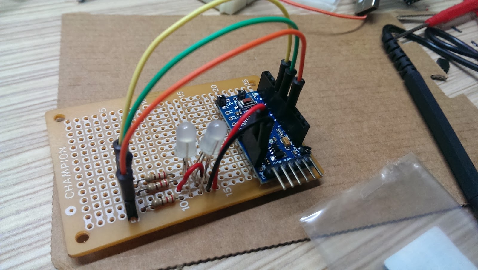
Here is the prototype in the photo below. In next tutorial, I will show you the 2nd phase to put everything together and install the whole system in the celling light. See you soon!
It's been a while since I wrote the RGB LED tutorial on my blog. Not sure if you have done yours.
If you would like to learn the whole project from the scratch, please visit these two tutorial first. - Tutorial 1 - Tutorial 2
Recently, I have found a night lamp laying around and we were not used it anymore. I thought, umm.. it might be a good idea to DIY RGB LED into this lamp. Let's get started!
This is what the lamp looks like below. It's powered up by a 9V/300mAh adapter. Since Arduino Mini Pro only take 5V or 3.3V, I had to replace a 5V/500mAh adapter from older 2G phones to use with this night lamp.
After I opened the light lamp, there was tiny PCB, few wires, and a very small lightbulb under the transparent cover. I removed most of stuff inside to make room for my Arduino board.
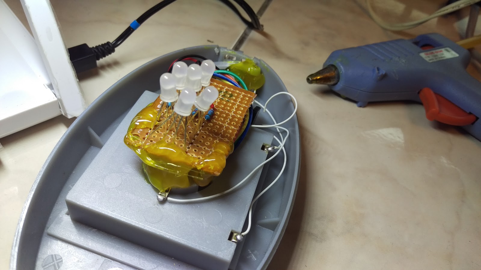
Since this is a night lamp, there is no need to let this lamp too bright. I decided to use 6 RGB LED to be the light source. Please refer to my RGB LED tutorial 1 to see the how to wire up.
After soldered the LEDs, resistors, and wires, I cut down extra LED legs to ensure they could fit into the lamp.
There were only few things to solder on Arduino Mini Pro pins with RGB LED and signal wires.
HC-05 Bluetooth Module wiring as follow:
TX connect to Arduino Pin 11(RX)
RX connect to Arduino Pin 12(TX)
Remember to connect TX on the HC-05 to RX on the Arduino and RX on the HC-05 to TX on the Arduino, so Arduino can receive data correctly.
VCC connect to 5V power
GND connect to Ground
All parts were soldered together; including Arduino, wires, RGB LED.
Then, I attached HC-05 Bluetooh module on the the Arduino Mini Pro.
** Remember to test it the whole thing to make sure it's working before you continue.**
I also cut the porto board in half to save more space below.
Look at the picture where I circled, I needed to keep the original connector to connect to Arduino Mini Pro, so the power plug can be inserted correctly into the lamp plug.
Here is the original PCB module come with the lamp. I just removed the connector with a plier instead of desoldering it. Believe me, I did try to desolder the connector from the PCB and it was really difficult for me, even with a tiny tool that sucked the soldering away from PCB.
There is a battery compartment under this night lamp. So I decided to put HC-05 Bluetooth module into this compartment to save space. By doing this, I had to insert 4 wires to go through the tiny hole in the center that was originally holding the light bulb. Since the thickness of the compartment door is quite thin, I could see the HC-05 Bluetooth LED indicator to see if it's connected or not! :) ** Fast flash: Not connected. ** Flash twice per 2 seconds: Connected.
After removed the light bulb, I was trying to find the perfect spot to place PCB and Arduino Mini Pro. By the way...I almost forgot to solder the connector back to the power wires.
Now, it's time to put all components inside the lamp. I decided to use hot glue to place the PCB with RGB LED on the center and inserted Arduino Mini Pro next to the screw column.
Secure the connector with the original screws and a lot glue to keep them in place using a hot glue gun.
More hot glue to ensure the PCB and connector to fix and secure.
Power it up! Cool, it's working now! I modified Arduino programming a little bit to set my PCB to light up with Blue color as soon as it powered up.
Finally, I placed the cover back and tighten two screws and it's done! This is my 2nd projects that really worked!
Now, I set next beside my children's bed to let him enjoy this magic night lamp and he loved it! :)
See the working video below:
END
Part III - Android HC-05 藍芽連線控制彩色 RGB LED: DIY 以手機控製夜燈
自從我把製作手機用藍芽搖控 RGB LED 彩色貼到部落格上,也有一段時間了。不知道你是否也依著步驟,DIY了你自己的呢?