In September 2014, I created this project with Arduino Mini Pro Mini and Android APP loved by so many readers! There are more than 100,000 App downloads by now! Since then, quite of few readers asked me how to change the sketch to be used on ESP32 with built-in Bluetooth. Here it is!! 😀
Be aware that LED PWM pins used on ESP32 were completely different, since Arduino Mini Pro and ESP32 have different architectures.
For ESP32, I used following pins:
Pin 13 = Red
Pin 12 = Green
Pin 14 = Blue
Caution: ESP32 does not allow to use pin 6, 7, 8, 9, 10, 11 or it will crash and reboot. I tried...😂
Also, there is no analogWrite() function in ESP32, so I need to change analogWrite() to ledcWrite() with
If you haven't seen my previous Arduino + Bluetooth + RGB LED tutorials, please check them out from here, before you start this one.
- Tutorial 1 Make the Arduino + Bluetooth + RGB LED - Tutorial 2 Make this App (older version) - Tutorial 3 Make a nigh lamp
In this tutorial, I will add RGB slider bar under the bottom of the App using App Inventor 2 (AI2) from MIT to allow users to adjust the particular LED brightness. This feature was requested by quite few of visitors. Hope you will enjoy this one!
For whatever reasons you do not want to do this yourself, please download this App from Google Play Store directly. It's FREE!
Screenshot of RGB LED Controller:
Here is screenshot of the component layout in App Inventor 2 for your reference.
First, let's initialize few variables in AI2.
Screen1.Initialize block is to reset App components status and set ColorPicked at x1, y1. The ColorPicked variable is used to store x1, y1 coordinates which are exact positions where users finger tip location on the display.
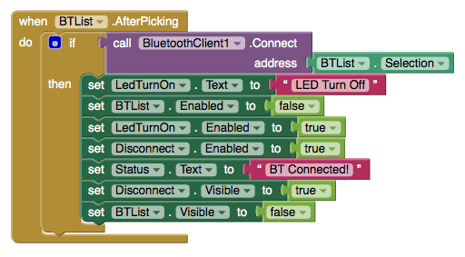
This part is considered as Bluetooth initialization to get nearby Bluetooth client list into the App.
After users select Arduino Bluetooth clients (Arduino + HC-05 + RGB module), this App set "Status.Text" to BT Connected and let user know the App has connected to Arduino successfully.
The block below turns the LED On/Off.
The block below will disconnect Bluetooth connection and reset component status.
This block sends Bluetooth command to Arduino after received color-code as well as save R, G, B color code value into a local Color_List2 (List is called Array in other programming languages)
The following three big blocks process the R, G, B sliders respectively.
Each time a slider's position changed, the App reflects the R/G/B value changed and save the value into Color_Code_to_BT variable and sends the new color code through SendBTCommend2 block to achange RGB LED color.
This block works the same as the one above except it only handle Green color value.
This block works the same as the one above except it only handle Blue color value.
When user's finger is touch or slide across the display, this SendBTCommend block will send R, G, B value accordingly to Arduino.
This SendBTCommend2 block is used to send RGB value to Arduino when R, G, or B value updated through R, G, B color sliders. The reason why I created this SendBTCommand2 to send R,G,B value was because there were different parameters needed to be processed before send BT command to Android phone.
The block blow is used to update RGB color to Arduion when user's finger touch on any part of the screen or in this case we only focus on the color wheel.
The block blow is used to update RGB color to Arduion when user's finger slide through the screen of the screen or in this case we only focus on the color wheel. This block is also where this App process rapid change of the LED colors!
Here is a video demonstration of this App:
You probably want to test this APP first before making it, correct? Please download the RGB LED Controller V3.0 with R/G/B Color slider from App Store. For people who already downloaded this App, you should be able to upgrade to this version directly from Google Play Store.
如果你不想自己動手做這個 APP, 請你到 Google Play Store 免費直接下載! 在本篇教學裡,我們將修改前一版的 V2.0 APP,使用 App Inventor 2 (AI2) 加入 R.G.B 三個顏色拉桿,讓使用者可以自行調整每個顏色的強度,進一步改變 LED 的顏色。會加入這個功能的主要原因是很多讀者都留言要求這個功能!讓我們開始動手吧!
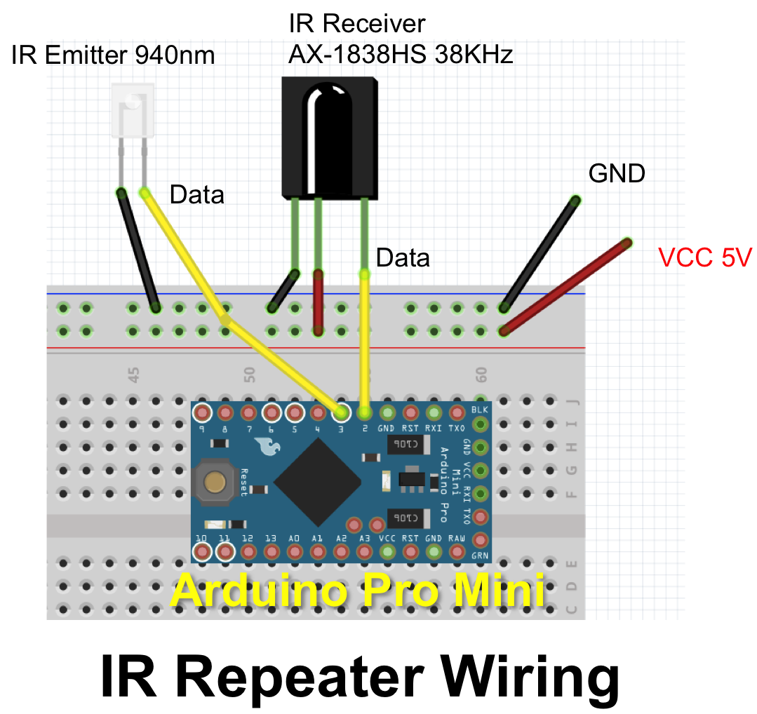
It's always a good practice to test out the wiring before solder components together.
Connect IR receiver LED to Arduino Pro Mini
Connect IR emitter LED through 100 Ohm resister
The program below was created by Lauszus that I found on Gighub. The original program was written to receive IR code and decode IR then save the IR code in the memory until a button is pressed to emit IR code. To meet my requirement, I made few modifications to make it receive IR, decode IR, and then emit the IR immediately. Here is my code:
[Programming code]
/*
 * IRrecord: record and play back IR signals as a minimal
 * An IR detector/demodulator must be connected to the input RECV_PIN.
 * An IR LED must be connected to the output PWM pin 3.
 * A button must be connected to the input BUTTON_PIN; this is the
 * send button.
 * A visible LED can be connected to STATUS_PIN to provide status.
 *
 * The logic is:
 * If the button is pressed, send the IR code.
 * If an IR code is received, record it.
 *
 * Version 0.11 September, 2009
 * Copyright 2009 Ken Shirriff
 * http://arcfn.com
 *
 *
 * Version 0.2 October, 2015
 * Modified to remove button function
 * This module acts a IR Repeater to just
 * "Read the IR Code " and "Send the IR Code" immediately
 * By En-Lin Chen / Stonez56
 *
 */

#include <IRremote.h>

int RECV_PIN = 2;
int STATUS_PIN = 13;

IRrecv irrecv(RECV_PIN);
IRsend irsend;

decode_results results;

void setup()
{
  Serial.begin(9600);
  irrecv.enableIRIn(); // Start the receiver
  pinMode(STATUS_PIN, OUTPUT);
}

// Storage for the recorded code
int codeType = -1; // The type of code
unsigned long codeValue; // The code value if not raw
unsigned int rawCodes[RAWBUF]; // The durations if raw
int codeLen; // The length of the code
int toggle = 0; // The RC5/6 toggle state

// Stores the code for later playback
// Most of this code is just logging
void storeCode(decode_results *results) {
  codeType = results->decode_type;
  int count = results->rawlen;
  if (codeType == UNKNOWN) {
    Serial.println("Received unknown code, saving as raw");
    codeLen = results->rawlen - 1;
    // To store raw codes:
    // Drop first value (gap)
    // Convert from ticks to microseconds
    // Tweak marks shorter, and spaces longer to cancel out IR receiver distortion
    for (int i = 1; i <= codeLen; i++) {
      if (i % 2) {
        // Mark
        rawCodes[i - 1] = results->rawbuf[i]*USECPERTICK - MARK_EXCESS;
        Serial.print(" m");
      }
      else {
        // Space
        rawCodes[i - 1] = results->rawbuf[i]*USECPERTICK + MARK_EXCESS;
        Serial.print(" s");
      }
      Serial.print(rawCodes[i - 1], DEC);
    }
    Serial.println("");
  }
  else {
    if (codeType == NEC) {
      Serial.print("Received NEC: ");
    }
    else if (codeType == SONY) {
      Serial.print("Received SONY: ");
    }
    else if (codeType == RC5) {
      Serial.print("Received RC5: ");
    }
    else if (codeType == RC6) {
      Serial.print("Received RC6: ");
    }
    else {
      Serial.print("Unexpected codeType ");
      Serial.print(codeType, DEC);
      Serial.println("");
    }
    Serial.println(results->value, HEX);
    codeValue = results->value;
    codeLen = results->bits;
  }
}

void sendCode(int repeat) {
  if(codeValue == 0xFFFFFFFF) return;  //ignore FFFFFFF IR code
  if (codeType == NEC) {
      irsend.sendNEC(codeValue, codeLen);
      Serial.print("Sent NEC ");
      Serial.println(codeValue, HEX);
  }
  else if (codeType == SONY) {
    irsend.sendSony(codeValue, codeLen);
    Serial.print("Sent Sony ");
    Serial.println(codeValue, HEX);
  }
  else if (codeType == RC5 || codeType == RC6) {
    if (!repeat) {
      // Flip the toggle bit for a new button press
      toggle = 1 - toggle;
    }
    // Put the toggle bit into the code to send
    codeValue = codeValue & ~(1 << (codeLen - 1));
    codeValue = codeValue | (toggle << (codeLen - 1));
    if (codeType == RC5) {
      Serial.print("Sent RC5 ");
      Serial.println(codeValue, HEX);
      irsend.sendRC5(codeValue, codeLen);
    }
    else {
      irsend.sendRC6(codeValue, codeLen);
      Serial.print("Sent RC6 ");
      Serial.println(codeValue, HEX);
    }
  }
  else if (codeType == UNKNOWN /* i.e. raw */) {
    // Assume 38 KHz
    irsend.sendRaw(rawCodes, codeLen, 38);
    Serial.println("Sent raw");
  }
}


void loop() {

  if (irrecv.decode(&results)) {
    /* Receive IR code */
    Serial.println("Pressed!");
    digitalWrite(STATUS_PIN, HIGH);
    storeCode(&results);
    irrecv.resume(); // resume receiver
    digitalWrite(STATUS_PIN, LOW);
    delay(50);

    /* Send IR code */
    Serial.println("Sending!");
    digitalWrite(STATUS_PIN, HIGH);
    sendCode(true);
    digitalWrite(STATUS_PIN, LOW);
    delay(50); // Wait a bit between retransmissions
    irrecv.enableIRIn(); // Re-start the receiver
    Serial.println("--------------------------------");
  }
}
After programming code is copied into Arduino IDE, upload it to your Arduino Pro Mini.
Power it up and then use any remote control to point to IR receiver and observe the Arduino IDE Serial output screen. Turn on Serial Monitor: Arduino -> Tools->Serial Monitor
Here shows you the IR command received through the serial port monitor.
Received NFC: FFA252D (Remote type is NEC, and the code is 0xFFA25D)
Sent NEC: FFA25D
After fully tested, it's time to solder everything together.
First, solder IR emitter LED to the extended long wires. Although not showing at the photo below, an 100 Omh resistor is needed on the data pin 2.
I soldered the IR receiver LED on small proton board to allow me to fix it into the IR BOX easier.
To provide constant power, I decided to use a smart phone power adaptor through a USB connector.
There are 4 tiny wires in the USB cable and you only need black and red wire to supply power to Arduino Pro Mini. Red connects to VCC and Black connects to Ground.
I've chosen to use a name card case as the enclosure. I drilled a tiny hole in the front of the name card case (see below), to expose IR receiver LED towards the edge.
Too often, accidentally pulling the wires will break the soldering part, so I tight a knot on the extended long wires to secure wires in place.
Now, every parts are soldered together as you see below.
Emitter board and Arduino Pro Mini placement is looked like this below.
Then, I glue the entire board with a glue gun to secure PCBs inside the name card box.
Plug the USB adaptor to power it up. Great! It's working.
Below is how this project looked like. As you can see, the extended wires are almost five to seven meters long.
Place IR BOX next to your TV and plug the USB adapter
Pull the IR emitter with the wire through the wall into the living room
Make sure the IR emitter is aiming towards the IR receiver on the Set Top Box
I glue the IR emitter LED next to my couch and it working fine
Done
After the setup, I've been use this IR repeater for 2~3 weeks and it's working perfectly without any issue. If you would like to make your own, you can follow this tutorial!