It's been a while since I published my last tutorial. This morning, when I checked MIT App Inventor 2 web editor, I found few new interesting new components.
One of them specially caught my eyes is the "SpeechRecognizer" under Media block.
Checked the explanation on the right, I decided to do a quick test on this new component.
What I want to do here is very simple:
Click "Speak" button to talk to the App
The App send the voice to SpeechRecognizer
The App then show the particular sentence into a Text next to "You've said"
Here is the Screen1 Layout:
Here are all the components I've used in this tutorial, a button, two labels, and SpeechRecognizer1 component as shown below.
Here are the programming blocks. Only few blocks to get the Speech Recognizer to work. I was very surprised!
First, initial varibles and text to blank or "".
Secondly, when "SpeakBTN" clicked, just call "SpeechRecognizer1" to GetText.
After get your Voice to Text, just set it to label.
Well, that's all need you do do the complete Voice Recognizer App.
See the YouTube Video for the demo below.
I guess you might want to give it a try now!
The End.
==================================================================
If you haven't seen my previous Arduino + Bluetooth + RGB LED tutorials, please check them out from here, before you start this one.
- Tutorial 1 Make the Arduino + Bluetooth + RGB LED - Tutorial 2 Make this App (older version) - Tutorial 3 Make a nigh lamp
In this tutorial, I will add RGB slider bar under the bottom of the App using App Inventor 2 (AI2) from MIT to allow users to adjust the particular LED brightness. This feature was requested by quite few of visitors. Hope you will enjoy this one!
For whatever reasons you do not want to do this yourself, please download this App from Google Play Store directly. It's FREE!
Screenshot of RGB LED Controller:
Here is screenshot of the component layout in App Inventor 2 for your reference.
First, let's initialize few variables in AI2.
Screen1.Initialize block is to reset App components status and set ColorPicked at x1, y1. The ColorPicked variable is used to store x1, y1 coordinates which are exact positions where users finger tip location on the display.
This part is considered as Bluetooth initialization to get nearby Bluetooth client list into the App.
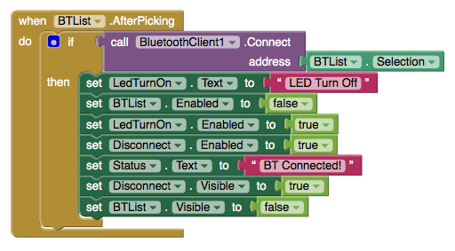
After users select Arduino Bluetooth clients (Arduino + HC-05 + RGB module), this App set "Status.Text" to BT Connected and let user know the App has connected to Arduino successfully.
The block below turns the LED On/Off.
The block below will disconnect Bluetooth connection and reset component status.
This block sends Bluetooth command to Arduino after received color-code as well as save R, G, B color code value into a local Color_List2 (List is called Array in other programming languages)
The following three big blocks process the R, G, B sliders respectively.
Each time a slider's position changed, the App reflects the R/G/B value changed and save the value into Color_Code_to_BT variable and sends the new color code through SendBTCommend2 block to achange RGB LED color.
This block works the same as the one above except it only handle Green color value.
This block works the same as the one above except it only handle Blue color value.
When user's finger is touch or slide across the display, this SendBTCommend block will send R, G, B value accordingly to Arduino.
This SendBTCommend2 block is used to send RGB value to Arduino when R, G, or B value updated through R, G, B color sliders. The reason why I created this SendBTCommand2 to send R,G,B value was because there were different parameters needed to be processed before send BT command to Android phone.
The block blow is used to update RGB color to Arduion when user's finger touch on any part of the screen or in this case we only focus on the color wheel.
The block blow is used to update RGB color to Arduion when user's finger slide through the screen of the screen or in this case we only focus on the color wheel. This block is also where this App process rapid change of the LED colors!
Here is a video demonstration of this App:
You probably want to test this APP first before making it, correct? Please download the RGB LED Controller V3.0 with R/G/B Color slider from App Store. For people who already downloaded this App, you should be able to upgrade to this version directly from Google Play Store.
如果你不想自己動手做這個 APP, 請你到 Google Play Store 免費直接下載! 在本篇教學裡,我們將修改前一版的 V2.0 APP,使用 App Inventor 2 (AI2) 加入 R.G.B 三個顏色拉桿,讓使用者可以自行調整每個顏色的強度,進一步改變 LED 的顏色。會加入這個功能的主要原因是很多讀者都留言要求這個功能!讓我們開始動手吧!
After few weeks of struggling with MIT App Inventor 2, I finally completed my second generation of Color LED Controller V2.0 App.
Basically, 2nd generation of Android APP shows a color RGB wheel on the display and you might pick any color on the display to wirelessly change the RGB color accordingly. With glide/drag capability built in the App, you may glide your finger through the color wheel to see RGB LED changes color gradually.
For the Arduino part, all the code stays the same. Yes, I haven't modified a single line of code in the Arduino.
4) Code for touch on the color wheel to change LED color
5) Code for Glide/Drag finger across the color wheel to see the color change accordingly
6) Here is the code for RGB color code split and then send to Arduino to change RGB LED color through Bluetooth.
How RGB Color Code was Processed:==*==*==*====*====*====*====*====*====*====*====*====*====*====*==
In App Inventor, the color code string after [Split Color]will be something like "(255 255 255 255)". What I need in Arduino is only R, G B, so I have to remove last 255.
*** The last 255 is a string in color code and it will be 255 all the time***
For easier string processing, I replace " "(space) with a "." (dot).
Then, I send each color code string to Arduino as "255.255.255)"
In side Arduino, I could split R, G, and B easily with the "."(dot) and use ending ")"(parenthesis) to check if the color code is complete or not.
==*==*==*====*====*====*====*====*====*====*====*====*====*====*==
After you put all these codes into MIT App Inventor 2, you should able to build the code on your PC/Mac to generate an Android .APK to place on your Android phone to test it out with Arduino.
Please do not ask me to post the original code here for you to download. If I do so, no one would download my App from Android Play Store! ;)