In September 2014, I created this project with Arduino Mini Pro Mini and Android APP loved by so many readers! There are more than 100,000 App downloads by now! Since then, quite of few readers asked me how to change the sketch to be used on ESP32 with built-in Bluetooth. Here it is!! 😀
Be aware that LED PWM pins used on ESP32 were completely different, since Arduino Mini Pro and ESP32 have different architectures.
For ESP32, I used following pins:
Pin 13 = Red
Pin 12 = Green
Pin 14 = Blue
Caution: ESP32 does not allow to use pin 6, 7, 8, 9, 10, 11 or it will crash and reboot. I tried...😂
Also, there is no analogWrite() function in ESP32, so I need to change analogWrite() to ledcWrite() with
It's been a while since I wrote the RGB LED tutorial on my blog. Not sure if you have done yours.
If you would like to learn the whole project from the scratch, please visit these two tutorial first. - Tutorial 1 - Tutorial 2
Recently, I have found a night lamp laying around and we were not used it anymore. I thought, umm.. it might be a good idea to DIY RGB LED into this lamp. Let's get started!
This is what the lamp looks like below. It's powered up by a 9V/300mAh adapter. Since Arduino Mini Pro only take 5V or 3.3V, I had to replace a 5V/500mAh adapter from older 2G phones to use with this night lamp.
After I opened the light lamp, there was tiny PCB, few wires, and a very small lightbulb under the transparent cover. I removed most of stuff inside to make room for my Arduino board.
Since this is a night lamp, there is no need to let this lamp too bright. I decided to use 6 RGB LED to be the light source. Please refer to my RGB LED tutorial 1 to see the how to wire up.
After soldered the LEDs, resistors, and wires, I cut down extra LED legs to ensure they could fit into the lamp.
There were only few things to solder on Arduino Mini Pro pins with RGB LED and signal wires.
HC-05 Bluetooth Module wiring as follow:
TX connect to Arduino Pin 11(RX)
RX connect to Arduino Pin 12(TX)
Remember to connect TX on the HC-05 to RX on the Arduino and RX on the HC-05 to TX on the Arduino, so Arduino can receive data correctly.
VCC connect to 5V power
GND connect to Ground
All parts were soldered together; including Arduino, wires, RGB LED.
Then, I attached HC-05 Bluetooh module on the the Arduino Mini Pro.
** Remember to test it the whole thing to make sure it's working before you continue.**
I also cut the porto board in half to save more space below.
Look at the picture where I circled, I needed to keep the original connector to connect to Arduino Mini Pro, so the power plug can be inserted correctly into the lamp plug.
Here is the original PCB module come with the lamp. I just removed the connector with a plier instead of desoldering it. Believe me, I did try to desolder the connector from the PCB and it was really difficult for me, even with a tiny tool that sucked the soldering away from PCB.
There is a battery compartment under this night lamp. So I decided to put HC-05 Bluetooth module into this compartment to save space. By doing this, I had to insert 4 wires to go through the tiny hole in the center that was originally holding the light bulb. Since the thickness of the compartment door is quite thin, I could see the HC-05 Bluetooth LED indicator to see if it's connected or not! :) ** Fast flash: Not connected. ** Flash twice per 2 seconds: Connected.
After removed the light bulb, I was trying to find the perfect spot to place PCB and Arduino Mini Pro. By the way...I almost forgot to solder the connector back to the power wires.
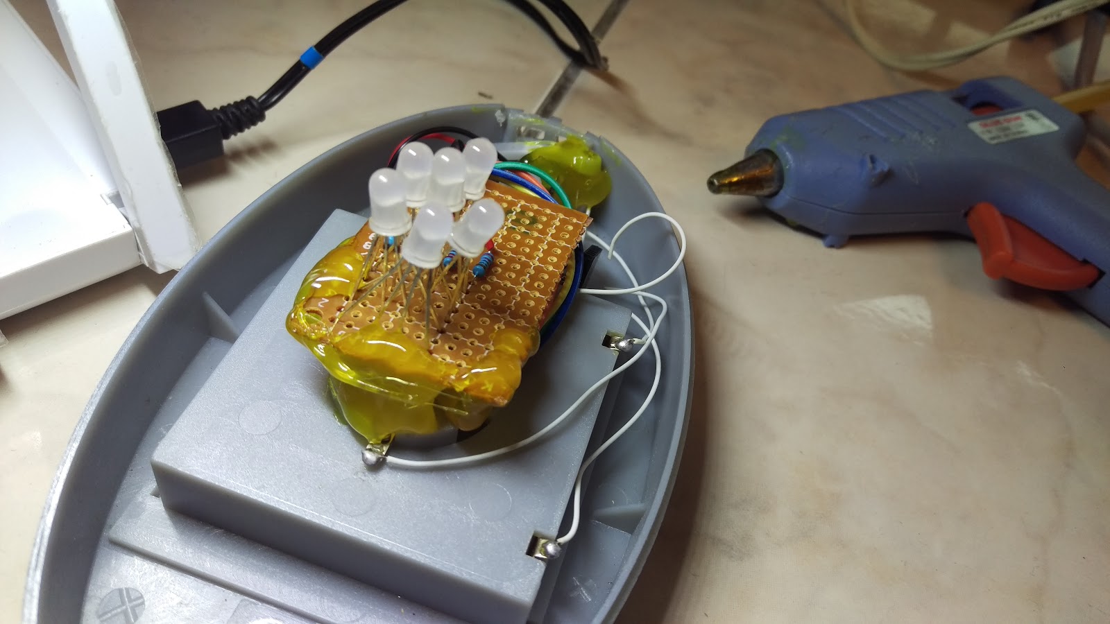
Now, it's time to put all components inside the lamp. I decided to use hot glue to place the PCB with RGB LED on the center and inserted Arduino Mini Pro next to the screw column.
Secure the connector with the original screws and a lot glue to keep them in place using a hot glue gun.
More hot glue to ensure the PCB and connector to fix and secure.
Power it up! Cool, it's working now! I modified Arduino programming a little bit to set my PCB to light up with Blue color as soon as it powered up.
Finally, I placed the cover back and tighten two screws and it's done! This is my 2nd projects that really worked!
Now, I set next beside my children's bed to let him enjoy this magic night lamp and he loved it! :)
See the working video below:
END
Part III - Android HC-05 藍芽連線控制彩色 RGB LED: DIY 以手機控製夜燈
自從我把製作手機用藍芽搖控 RGB LED 彩色貼到部落格上,也有一段時間了。不知道你是否也依著步驟,DIY了你自己的呢?
After few weeks of struggling with MIT App Inventor 2, I finally completed my second generation of Color LED Controller V2.0 App.
Basically, 2nd generation of Android APP shows a color RGB wheel on the display and you might pick any color on the display to wirelessly change the RGB color accordingly. With glide/drag capability built in the App, you may glide your finger through the color wheel to see RGB LED changes color gradually.
For the Arduino part, all the code stays the same. Yes, I haven't modified a single line of code in the Arduino.
4) Code for touch on the color wheel to change LED color
5) Code for Glide/Drag finger across the color wheel to see the color change accordingly
6) Here is the code for RGB color code split and then send to Arduino to change RGB LED color through Bluetooth.
How RGB Color Code was Processed:==*==*==*====*====*====*====*====*====*====*====*====*====*====*==
In App Inventor, the color code string after [Split Color]will be something like "(255 255 255 255)". What I need in Arduino is only R, G B, so I have to remove last 255.
*** The last 255 is a string in color code and it will be 255 all the time***
For easier string processing, I replace " "(space) with a "." (dot).
Then, I send each color code string to Arduino as "255.255.255)"
In side Arduino, I could split R, G, and B easily with the "."(dot) and use ending ")"(parenthesis) to check if the color code is complete or not.
==*==*==*====*====*====*====*====*====*====*====*====*====*====*==
After you put all these codes into MIT App Inventor 2, you should able to build the code on your PC/Mac to generate an Android .APK to place on your Android phone to test it out with Arduino.
Please do not ask me to post the original code here for you to download. If I do so, no one would download my App from Android Play Store! ;)