I have been attracted to Arduino POV[1] for quite a while, but I didn't have a chance to actually make it myself. Luckily, I found this easy to follow Arduino POV tutorial[2] on Instructable.com and within an hour, my son and me made two Arduino POV sets and have fun for the entire afternoon.
Material needed for this tutorial:
Arduino Nano * 1 (All other kinds of Arduino board will do)
LED * 7
220 resistor * 7
Jump wire ~ up to 10 (female to male)
Prefboard * 1
Battery pack (If you would like have fun without tethered with USB)
USB power to Nano USB port to supply power (or use a battery back to supply power)
Schematic: (I use www.tinkercad.com to draw this schematic below, just in case you interested.)
This is a fun a easy project! First, just connect LED cathode(negative) and resistors on the prefboard.
Then Preboard GND to Arduino Nano GND.
Then connect these LED positive pins to Arduino Nano.
As you can see in the picture below, I'v used Arduino Nano. It's lighter and smaller for portable devices. I made the Red one and my son have choose the Green.
Programming logic:
When anyone sees an image, the image stays in the retina of the eyes for roughly 1/16th seconds. We can utilize the particular physical characteristic of human eyes, to crate the Arduino POV project. The basic idea is when we want to show a letter, Arduino shows each column of a letter at a time to form the letter to eyes.
See the illustration below on how to show a letter 'H'. First, Arduino displays column 1 to light up all 7 LEDs at timing 1. While column 1 image stays in human eyes, Arduino shows 2nd column, then 3, 4, and 5th columns at their respectively timing 2~5. Since all these images stays in human eyes temporarily, we will see the letter 'H'.
Actual LED image captured:
Arduino code here:
Just copy and past into Arduino IDE and it should work. *Change your own message in the variable msgBody and remember to change msgLength*
/*
 Written by Ahmad Saeed on 22 August 2015

 This code is capable of displaying the following characters;
 0123456789ABCDEFGHIJKLMNOPQRSTUVWXYZ .-_!%&#$,()@?
*/

//////////////////// Message to Customize  ///////////////////
#define msgLength 11                                       ///
String msgBody = "This is POV";                            ///
//////////////////////////////////////////////////////////////
//////////////////////////////////////////////////////////////


#define delayInChar 3
#define delayBetweenChar 5
#define LED1 2
#define LED2 3
#define LED3 4
#define LED4 5
#define LED5 6
#define LED6 7
#define LED7 8

byte msgCode[(5 * msgLength) + 10];
boolean pintState;
int columnNum = -1;
String charToWrite;

void setup() {
  msgBody.toUpperCase();
  pinMode(LED1, OUTPUT);
  pinMode(LED2, OUTPUT);
  pinMode(LED3, OUTPUT);
  pinMode(LED4, OUTPUT);
  pinMode(LED5, OUTPUT);
  pinMode(LED6, OUTPUT);
  pinMode(LED7, OUTPUT);
}

void loop() {
//// Convert all text to binary array ////////////////////////
  if ( columnNum == -1 ) // This block needs to be done once//
  {                                                         //
    for (int c = 0; c < (msgBody.length()); c++)  {         //
      //Separate the following character                    //
      charToWrite = msgBody.substring(c, c + 1);            //
      //Send the separated characted to addChar function    //
      addChar(charToWrite);                                 //
    }                                                       //
      //Add a little space after each character             //
    addChar(" ");                                           //
    addChar(" ");                                           //
  }                                                         //
//////////////////////////////////////////////////////////////

//// Display the binary arrays after all characters are coded //
  for (int c = 0; c < (sizeof(msgCode)); c++)  {              //
    pintState = (msgCode[c] / B1000000) % B10;                //
    digitalWrite(LED1, pintState);                            //
                                                              //
    pintState = (msgCode[c] / B100000) % B10;                 //
    digitalWrite(LED2, pintState);                            //
                                                              //
    pintState = (msgCode[c] / B10000) % B10;                  //
    digitalWrite(LED3, pintState);                            //
                                                              //
    pintState = (msgCode[c] / B1000) % B10;                   //
    digitalWrite(LED4, pintState);                            //
                                                              //
    pintState = (msgCode[c] / B100) % B10;                    //
    digitalWrite(LED5, pintState);                            //
                                                              //
    pintState = (msgCode[c] / B10) % B10;                     //
    digitalWrite(LED6, pintState);                            //
                                                              //
    pintState = msgCode[c] % B10;;                            //
    digitalWrite(LED7, pintState);                            //
                                                              //
    delay(delayInChar);                                       //
    // if the character is finished, take a longer off period //
    if ((c + 1) % 5 == 0 ) {                                  //
      digitalWrite(LED1, LOW);                                //
      digitalWrite(LED2, LOW);                                //
      digitalWrite(LED3, LOW);                                //
      digitalWrite(LED4, LOW);                                //
      digitalWrite(LED5, LOW);                                //
      digitalWrite(LED6, LOW);                                //
      digitalWrite(LED7, LOW);                                //
      delay(delayBetweenChar);                                //
    }                                                         //
  }                                                           //
                                                              //
////////////////////////////////////////////////////////////////
}


void addChar(String y) {
  if (y == "1") {
    addColumn(B0010001);
    addColumn(B0100001);
    addColumn(B1111111);
    addColumn(B0000001);
    addColumn(B0000001);
  }
  else if (y == "2") {
    addColumn(B0100001);
    addColumn(B1000011);
    addColumn(B1000101);
    addColumn(B1001001);
    addColumn(B0110001);
  }
  else if (y == "3") {
    addColumn(B0100010);
    addColumn(B1000001);
    addColumn(B1001001);
    addColumn(B1001001);
    addColumn(B0110110);
  }
  else if (y == "4") {
    addColumn(B0001100);
    addColumn(B0010100);
    addColumn(B0100100);
    addColumn(B1111111);
    addColumn(B0000100);
  }
  else if (y == "5") {
    addColumn(B1110010);
    addColumn(B1010001);
    addColumn(B1010001);
    addColumn(B1010001);
    addColumn(B1001110);
  }
  else if (y == "6") {
    addColumn(B0111110);
    addColumn(B1001001);
    addColumn(B1001001);
    addColumn(B1001001);
    addColumn(B0100110);
  }
  else if (y == "7") {
    addColumn(B1000000);
    addColumn(B1000111);
    addColumn(B1001000);
    addColumn(B1010000);
    addColumn(B1100000);
  }
  else if (y == "8") {
    addColumn(B0110110);
    addColumn(B1001001);
    addColumn(B1001001);
    addColumn(B1001001);
    addColumn(B0110110);
  }
  else if (y == "9") {
    addColumn(B0110010);
    addColumn(B1001001);
    addColumn(B1001001);
    addColumn(B1001001);
    addColumn(B0111110);
  }
  else if (y == "0") {
    addColumn(B0111110);
    addColumn(B1000101);
    addColumn(B1001001);
    addColumn(B1010001);
    addColumn(B0111110);
  }
  else if (y == "A") {
    addColumn(B0011111);
    addColumn(B0100100);
    addColumn(B1000100);
    addColumn(B1000100);
    addColumn(B1111111);
  }
  else if (y == "B") {
    addColumn(B1111111);
    addColumn(B1001001);
    addColumn(B1001001);
    addColumn(B1001001);
    addColumn(B0110110);
  }
  else if (y == "C") {
    addColumn(B0111110);
    addColumn(B1000001);
    addColumn(B1000001);
    addColumn(B1000001);
    addColumn(B0100010);
  }
  else if (y == "D") {
    addColumn(B1111111);
    addColumn(B1000001);
    addColumn(B1000001);
    addColumn(B1000001);
    addColumn(B0111110);
  }
  else if (y == "E") {
    addColumn(B1111111);
    addColumn(B1001001);
    addColumn(B1001001);
    addColumn(B1001001);
    addColumn(B1000001);
  }
  else if (y == "F") {
    addColumn(B1111111);
    addColumn(B1001000);
    addColumn(B1001000);
    addColumn(B1001000);
    addColumn(B1000000);
  }
  else if (y == "G") {
    addColumn(B0111110);
    addColumn(B1000001);
    addColumn(B1000001);
    addColumn(B1000101);
    addColumn(B0100110);
  }
  else if (y == "H") {
    addColumn(B1111111);
    addColumn(B0001000);
    addColumn(B0001000);
    addColumn(B0001000);
    addColumn(B1111111);
  }
  else if (y == "I") {
    addColumn(B0000000);
    addColumn(B1000001);
    addColumn(B1111111);
    addColumn(B1000001);
    addColumn(B0000000);
  }
  else if (y == "J") {
    addColumn(B0000000);
    addColumn(B0000010);
    addColumn(B1000001);
    addColumn(B1000001);
    addColumn(B1111110);
  }
  else if (y == "K") {
    addColumn(B1111111);
    addColumn(B0001000);
    addColumn(B0010100);
    addColumn(B0100010);
    addColumn(B1000001);
  }
  else if (y == "L") {
    addColumn(B1111111);
    addColumn(B0000001);
    addColumn(B0000001);
    addColumn(B0000001);
    addColumn(B0000001);
  }
  else if (y == "M") {
    addColumn(B1111111);
    addColumn(B0100000);
    addColumn(B0011000);
    addColumn(B0100000);
    addColumn(B1111111);
  }
  else if (y == "N") {
    addColumn(B1111111);
    addColumn(B0010000);
    addColumn(B0001000);
    addColumn(B0000100);
    addColumn(B1111111);
  }
  else if (y == "O") {
    addColumn(B0111110);
    addColumn(B1000001);
    addColumn(B1000001);
    addColumn(B1000001);
    addColumn(B0111110);
  }
  else if (y == "P") {
    addColumn(B1111111);
    addColumn(B1001000);
    addColumn(B1001000);
    addColumn(B1001000);
    addColumn(B0110000);
  }
  else if (y == "Q") {
    addColumn(B0111100);
    addColumn(B1000010);
    addColumn(B1000010);
    addColumn(B1000010);
    addColumn(B0111101);
  }
  else if (y == "R") {
    addColumn(B1111111);
    addColumn(B1001000);
    addColumn(B1001100);
    addColumn(B1001010);
    addColumn(B0110001);
  }
  else if (y == "S") {
    addColumn(B0110010);
    addColumn(B1001001);
    addColumn(B1001001);
    addColumn(B1001001);
    addColumn(B0100110);
  }
  else if (y == "T") {
    addColumn(B1000000);
    addColumn(B1000000);
    addColumn(B1111111);
    addColumn(B1000000);
    addColumn(B1000000);
  }
  else if (y == "U") {
    addColumn(B1111110);
    addColumn(B0000001);
    addColumn(B0000001);
    addColumn(B0000001);
    addColumn(B1111110);
  }
  else if (y == "V") {
    addColumn(B1111100);
    addColumn(B0000010);
    addColumn(B0000001);
    addColumn(B0000010);
    addColumn(B1111100);
  }
  else if (y == "W") {
    addColumn(B1111110);
    addColumn(B0000001);
    addColumn(B0000110);
    addColumn(B0000001);
    addColumn(B1111110);
  }
  else if (y == "X") {
    addColumn(B1100011);
    addColumn(B0010100);
    addColumn(B0001000);
    addColumn(B0010100);
    addColumn(B1100011);
  }
  else if (y == "Y") {
    addColumn(B1110000);
    addColumn(B0001000);
    addColumn(B0001111);
    addColumn(B0001000);
    addColumn(B1110000);
  }
  else if (y == "Z") {
    addColumn(B1000011);
    addColumn(B1000101);
    addColumn(B1001001);
    addColumn(B1010001);
    addColumn(B1000011);
  }
  else if (y == "Z") {
    addColumn(B1000011);
    addColumn(B1000101);
    addColumn(B1001001);
    addColumn(B1010001);
    addColumn(B1000011);
  }
  else if (y == " ") {
    addColumn(B0000000);
    addColumn(B0000000);
    addColumn(B0000000);
    addColumn(B0000000);
    addColumn(B0000000);
  }
  else if (y == ".") {
    addColumn(B0000000);
    addColumn(B0000011);
    addColumn(B0000011);
    addColumn(B0000000);
    addColumn(B0000000);
  }
  else if (y == "_") {
    addColumn(B0000001);
    addColumn(B0000001);
    addColumn(B0000001);
    addColumn(B0000001);
    addColumn(B0000001);
  }
  else if (y == "-") {
    addColumn(B0000000);
    addColumn(B0001000);
    addColumn(B0001000);
    addColumn(B0001000);
    addColumn(B0000000);
  }
  else if (y == "!") {
    addColumn(B0000000);
    addColumn(B0000000);
    addColumn(B1111101);
    addColumn(B0000000);
    addColumn(B0000000);
  }
  else if (y == "(") {
    addColumn(B0000000);
    addColumn(B0000000);
    addColumn(B0000000);
    addColumn(B0111110);
    addColumn(B1000001);
  }
  else if (y == ")") {
    addColumn(B1000001);
    addColumn(B0111110);
    addColumn(B0000000);
    addColumn(B0000000);
    addColumn(B0000000);
  }
  else if (y == "%") {
    addColumn(B1100010);
    addColumn(B1100100);
    addColumn(B0001000);
    addColumn(B0010011);
    addColumn(B0100011);
  }
  else if (y == ",") {
    addColumn(B0000000);
    addColumn(B0000101);
    addColumn(B0000110);
    addColumn(B0000000);
    addColumn(B0000000);
  }
  else if (y == "?") {
    addColumn(B0100000);
    addColumn(B1000101);
    addColumn(B1001000);
    addColumn(B0110000);
    addColumn(B0000000);
  }
  else if (y == "#") {
    addColumn(B0010100);
    addColumn(B0111110);
    addColumn(B0010100);
    addColumn(B0111110);
    addColumn(B0010100);
  }
  else if (y == "@") {
    addColumn(B0111110);
    addColumn(B1000001);
    addColumn(B1011101);
    addColumn(B1011101);
    addColumn(B0111000);
  }
  else if (y == "$") {
    addColumn(B0110010);
    addColumn(B1001001);
    addColumn(B1111111);
    addColumn(B1001001);
    addColumn(B0100110);
  }
}

void addColumn(byte x) {
  columnNum += 1;
  msgCode[columnNum] = (x);
}
Image captured with my POV set:
Image captured with my son's POV set:
How to capture the image:
I used HTC U11 to shot these photos. First, you have change HTC camera to Pro mode and set the exposure time to greater than 2 seconds to capture this image. Hold the Arduino POV set steadily on one hand and move the POV set slowly towards to left from right. I believe any camera with Bulb exposure time greater than 2 seconds should be able to capture this image.
It's always a good practice to test out the wiring before solder components together.
Connect IR receiver LED to Arduino Pro Mini
Connect IR emitter LED through 100 Ohm resister
The program below was created by Lauszus that I found on Gighub. The original program was written to receive IR code and decode IR then save the IR code in the memory until a button is pressed to emit IR code. To meet my requirement, I made few modifications to make it receive IR, decode IR, and then emit the IR immediately. Here is my code:
[Programming code]
/*
 * IRrecord: record and play back IR signals as a minimal
 * An IR detector/demodulator must be connected to the input RECV_PIN.
 * An IR LED must be connected to the output PWM pin 3.
 * A button must be connected to the input BUTTON_PIN; this is the
 * send button.
 * A visible LED can be connected to STATUS_PIN to provide status.
 *
 * The logic is:
 * If the button is pressed, send the IR code.
 * If an IR code is received, record it.
 *
 * Version 0.11 September, 2009
 * Copyright 2009 Ken Shirriff
 * http://arcfn.com
 *
 *
 * Version 0.2 October, 2015
 * Modified to remove button function
 * This module acts a IR Repeater to just
 * "Read the IR Code " and "Send the IR Code" immediately
 * By En-Lin Chen / Stonez56
 *
 */

#include <IRremote.h>

int RECV_PIN = 2;
int STATUS_PIN = 13;

IRrecv irrecv(RECV_PIN);
IRsend irsend;

decode_results results;

void setup()
{
  Serial.begin(9600);
  irrecv.enableIRIn(); // Start the receiver
  pinMode(STATUS_PIN, OUTPUT);
}

// Storage for the recorded code
int codeType = -1; // The type of code
unsigned long codeValue; // The code value if not raw
unsigned int rawCodes[RAWBUF]; // The durations if raw
int codeLen; // The length of the code
int toggle = 0; // The RC5/6 toggle state

// Stores the code for later playback
// Most of this code is just logging
void storeCode(decode_results *results) {
  codeType = results->decode_type;
  int count = results->rawlen;
  if (codeType == UNKNOWN) {
    Serial.println("Received unknown code, saving as raw");
    codeLen = results->rawlen - 1;
    // To store raw codes:
    // Drop first value (gap)
    // Convert from ticks to microseconds
    // Tweak marks shorter, and spaces longer to cancel out IR receiver distortion
    for (int i = 1; i <= codeLen; i++) {
      if (i % 2) {
        // Mark
        rawCodes[i - 1] = results->rawbuf[i]*USECPERTICK - MARK_EXCESS;
        Serial.print(" m");
      }
      else {
        // Space
        rawCodes[i - 1] = results->rawbuf[i]*USECPERTICK + MARK_EXCESS;
        Serial.print(" s");
      }
      Serial.print(rawCodes[i - 1], DEC);
    }
    Serial.println("");
  }
  else {
    if (codeType == NEC) {
      Serial.print("Received NEC: ");
    }
    else if (codeType == SONY) {
      Serial.print("Received SONY: ");
    }
    else if (codeType == RC5) {
      Serial.print("Received RC5: ");
    }
    else if (codeType == RC6) {
      Serial.print("Received RC6: ");
    }
    else {
      Serial.print("Unexpected codeType ");
      Serial.print(codeType, DEC);
      Serial.println("");
    }
    Serial.println(results->value, HEX);
    codeValue = results->value;
    codeLen = results->bits;
  }
}

void sendCode(int repeat) {
  if(codeValue == 0xFFFFFFFF) return;  //ignore FFFFFFF IR code
  if (codeType == NEC) {
      irsend.sendNEC(codeValue, codeLen);
      Serial.print("Sent NEC ");
      Serial.println(codeValue, HEX);
  }
  else if (codeType == SONY) {
    irsend.sendSony(codeValue, codeLen);
    Serial.print("Sent Sony ");
    Serial.println(codeValue, HEX);
  }
  else if (codeType == RC5 || codeType == RC6) {
    if (!repeat) {
      // Flip the toggle bit for a new button press
      toggle = 1 - toggle;
    }
    // Put the toggle bit into the code to send
    codeValue = codeValue & ~(1 << (codeLen - 1));
    codeValue = codeValue | (toggle << (codeLen - 1));
    if (codeType == RC5) {
      Serial.print("Sent RC5 ");
      Serial.println(codeValue, HEX);
      irsend.sendRC5(codeValue, codeLen);
    }
    else {
      irsend.sendRC6(codeValue, codeLen);
      Serial.print("Sent RC6 ");
      Serial.println(codeValue, HEX);
    }
  }
  else if (codeType == UNKNOWN /* i.e. raw */) {
    // Assume 38 KHz
    irsend.sendRaw(rawCodes, codeLen, 38);
    Serial.println("Sent raw");
  }
}


void loop() {

  if (irrecv.decode(&results)) {
    /* Receive IR code */
    Serial.println("Pressed!");
    digitalWrite(STATUS_PIN, HIGH);
    storeCode(&results);
    irrecv.resume(); // resume receiver
    digitalWrite(STATUS_PIN, LOW);
    delay(50);

    /* Send IR code */
    Serial.println("Sending!");
    digitalWrite(STATUS_PIN, HIGH);
    sendCode(true);
    digitalWrite(STATUS_PIN, LOW);
    delay(50); // Wait a bit between retransmissions
    irrecv.enableIRIn(); // Re-start the receiver
    Serial.println("--------------------------------");
  }
}
After programming code is copied into Arduino IDE, upload it to your Arduino Pro Mini.
Power it up and then use any remote control to point to IR receiver and observe the Arduino IDE Serial output screen. Turn on Serial Monitor: Arduino -> Tools->Serial Monitor
Here shows you the IR command received through the serial port monitor.
Received NFC: FFA252D (Remote type is NEC, and the code is 0xFFA25D)
Sent NEC: FFA25D
After fully tested, it's time to solder everything together.
First, solder IR emitter LED to the extended long wires. Although not showing at the photo below, an 100 Omh resistor is needed on the data pin 2.
I soldered the IR receiver LED on small proton board to allow me to fix it into the IR BOX easier.
To provide constant power, I decided to use a smart phone power adaptor through a USB connector.
There are 4 tiny wires in the USB cable and you only need black and red wire to supply power to Arduino Pro Mini. Red connects to VCC and Black connects to Ground.
I've chosen to use a name card case as the enclosure. I drilled a tiny hole in the front of the name card case (see below), to expose IR receiver LED towards the edge.
Too often, accidentally pulling the wires will break the soldering part, so I tight a knot on the extended long wires to secure wires in place.
Now, every parts are soldered together as you see below.
Emitter board and Arduino Pro Mini placement is looked like this below.
Then, I glue the entire board with a glue gun to secure PCBs inside the name card box.
Plug the USB adaptor to power it up. Great! It's working.
Below is how this project looked like. As you can see, the extended wires are almost five to seven meters long.
Place IR BOX next to your TV and plug the USB adapter
Pull the IR emitter with the wire through the wall into the living room
Make sure the IR emitter is aiming towards the IR receiver on the Set Top Box
I glue the IR emitter LED next to my couch and it working fine
Done
After the setup, I've been use this IR repeater for 2~3 weeks and it's working perfectly without any issue. If you would like to make your own, you can follow this tutorial!
To share a Set Top Box in living room with Bedroom TV using the same Remote Control.
Preface:
Recently, I subscribed a VOD (Video On Demand) service that came with a Set Top Box in the living room. However, I would like to occasionally watch VOD in the bedroom, but the Set Top Box is in the living room. As you know, there is no way to control the Set Top Box in the living room from the bedroom. Yeah, an IR repeater is all I need. There are commercial products available in the market already, but I quickly thought about the Control celling light with a TV remote Arduino project I have done before might be an replacement for the IR repeater I need. After all, this is why I learn Arduino - May my life easier!!
Drawbacks of this project:
Either one VOD TV program can be watched from living or bedroom at a time, since the Set Top Box is shared.
Arduino Programming Logic:
The programming logic to repeat the IR signal is quite simple
Receive remote control signal from IR receiver
Decode the IR code
Send the decoded IR code from the IR emitter
IR Repeater Setup Illustration:
The illustration below shows you how the whole IR Repeater is setup in my apartment to share Set Top Box in two rooms.
Living Room TV
Bedroom TV
Set Top Box (HDMI out connect to a HDMI switch, yes you need this!)
HDMI cable from Set Top Box to bedroom TV
Arduino IR Box
IR Emitter
A hole on the wall
* The IR remotes shown below are actually the same remote
Working IR Repeater Prototype Video:
See the working prototype in the video below. As you can see, even through the IR repeater, the Set Top Box response time is fairly quick!
Material Needed:
Arduino Mini Pro
IR Emitter 940nm * 1
IR Receiver LED, Aixin AX-1838HS 38KHz * 1 (Other brand 38KHz should work)
ProtoBoard * 1
100 ohm resistor * 1
Short Jump wires * 10
5 meter long single wires * 2
LED Lineup:
Starts from the left: IR LED receiver, IR LED emitter, green LED, and red LED.
In the end, I didn't use red and green and LED, but relied on the Arduino built-in red LED on pin 13 and Serial port green LED in this project.
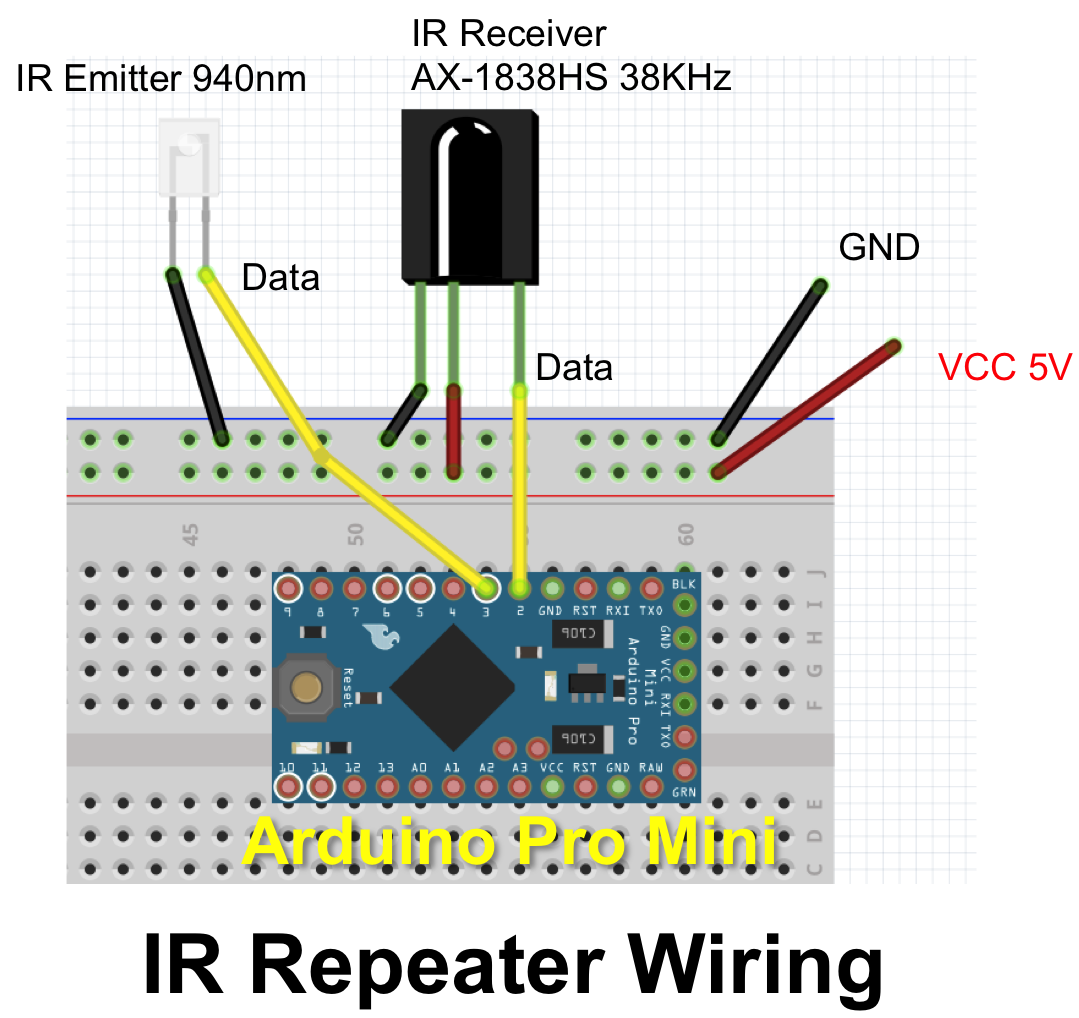
IR Repeater Wiring:
Wiring up is quite easy as you can see below. (I forgot to draw the 100 Ohm resistor in the illustration below, but you need it.)
IR Emitter GND to GND
IR Emitter Data to 100 Ohm resistor to Arduino pin 3
IR Receiver Data to Arduino pin 2
IR Receiver GND to Arduino GND
IR Receiver VCC to Arduino VCC
Proton board GND to power source GND
Proton board VCC to power source VCC (USB power adapter)
In part 2, I will show you how I made the IR Repeater box, schematic, and Arduino code I modified from github by Lauszus. If you are interested, you may take a look at the code first.