In this tutorial, I will show you how to make a Voice Control Color Lighting with Google Home or Google Assistant. I used a NODEMCU ESP-12E V2.0 and WS2812B LED strips for this project.
Preface:
In last tutorial, I had showed you how to make a Voice Control Light Switch with Google Home or Google Assistant. Not sure if you have chance to try to do this yourself or not. The previous tutorials
are considered a prerequisite for this tutorial. Please checkout previous tutorials from here:
Goal:
Use voice command to say “Set Color Light” + color to change the light colors.
For example: If you said “Set color light red”, the lighting will change from current color to “red”.
Very sample!
Although turn on/off light switch with voice is quite practical in daily life, it’s somehow not so interesting. In this tutorial, you will be able to change the lighting color with voice.
Components needed:
- NODEMCU ESP-12E V2.0 * 1
- WS2812B RGB LED Strips – two meters (120 LEDs) * 1
- Few jumper wires
- 220 resistors * 4
- 1000uF capacitor * 1 (Not used in this tutorial. place this capacitor near NODEMCU)
- 110V 5V/2.4A power adapter * 1
- Core of paper towel * 3
- Double sided tapes
- Hot glue
- A large white semi-transparent plastic cardboard


1. Get three core of paper towers and stack them like this at the predefined length. Glue them with hot glue.
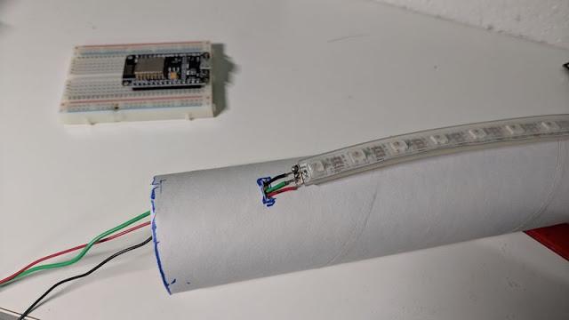
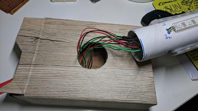
2. Cut WS2812B LED strip into four pieces with 30 LED each. Solder three wires on each WS2812B LED strip; Red for + pin; Black for – pin; Green for data pin. Then, cut small holes on the bottom of the paper tower core. This is used for the wire to go through.
3. Glue four LED strips on the paper tower core with double sided tape and let wires go inside the paper tower core. So we could collect all wires to the base for easier connections.

4. Here I used a thicker paper box as the base and cut a hole on the center top. Also, I fill the inside with Styrofoam to make the base more stable. Then, drill a hole that’s roughly the diameter of the paper tower core.
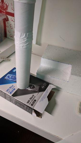
5. Place the paper tower core into the hole of the paper box.
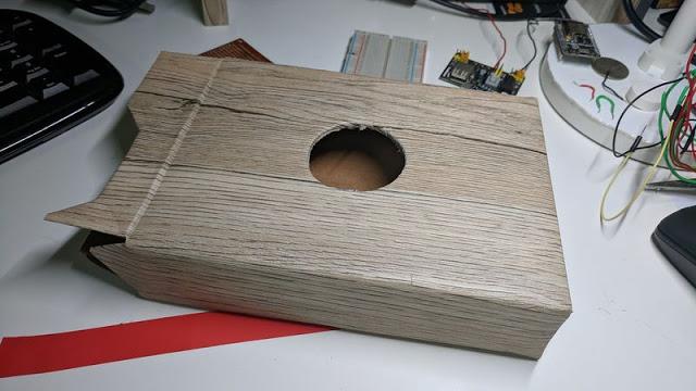
6. To decorate the base, I used wooden color paper sticker to wrap around the paper box. It does look better!
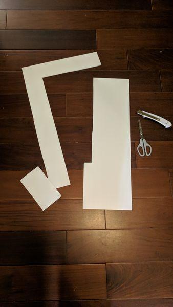
7. Cut white plastic cardboard into equal length that’s roughly longer than the total height of the paper tower core.

8. Glue these white plastic cardboard into a long squared tube as shown.
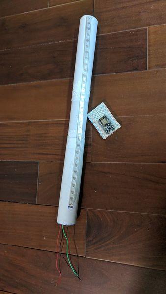
9.Insert the paper tower core with LED strips into the base with all the wires to go through the paper box base.
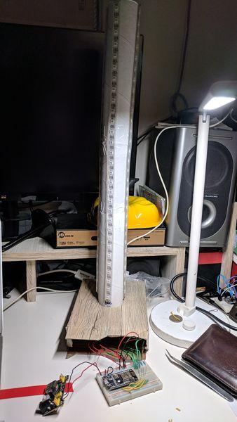
11. Here is the almost completed LED lighting unit
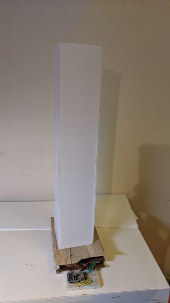
12. Now, place the white plastic square tube on the paper tower core to diffuse the LED colors.
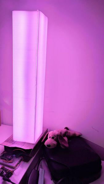
13. Light it up. It looks pretty good!

PS: I reused a 5V/2.4A old power adapter. I think this is bright enough for the LED lighting. Do not use 5V/1A or 5V/1.5A for this project, the light will be incorrect and very dim.
-
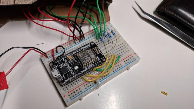
Connection:
This video shows you the detailed connections on NODEMCU and WS2812B LED strips.
Connection:
- Red to 5V+ (total 4 pins from LED strips)
- Black to GND (total 4 pins from LED strips)
- Green to NODEMCU data pins ((total 4 pins from LED strips; D2,D3,D4,D5)
- NodeMCU VIN to 5V+
- NodeMCU GND to power Adapter GND (Share GND)
- 5V/2.4A power adapter to 5V+
- 5V/2.4A power adapter to GND
- 1000uF Capacitor parallel with the power adapter (Not in this tutorial, since I haven't purchase this yet :)
Programming codes:
/***************************************************
  Adafruit MQTT Library ESP8266 Adafruit IO SSL/TLS example
  Must use the latest version of ESP8266 Arduino from:
    https://github.com/esp8266/Arduino
  Works great with Adafruit's Huzzah ESP board & Feather
  ---- https://www.adafruit.com/product/2471
  ---- https://www.adafruit.com/products/2821
  Adafruit invests time and resources providing this open source code,
  please support Adafruit and open-source hardware by purchasing
  products from Adafruit!
  Written by Tony DiCola for Adafruit Industries.
  SSL/TLS additions by Todd Treece for Adafruit Industries.
  MIT license, all text above must be included in any redistribution
 ****************************************************/
#include <ESP8266WiFi.h>
#include "Adafruit_MQTT.h"
#include "Adafruit_MQTT_Client.h"

//This line allows one to use NODEMCU pin name, such as D0
#define FASTLED_ESP8266_RAW_PIN_ORDER
#include <FastLED.h>
#include <Wire.h>


// Information about the LED strip itself

#define LED_PIN1     D3
#define LED_PIN2     D4
#define LED_PIN3     D5
#define LED_PIN4     D6
#define COLOR_ORDER GRB
#define CHIPSET     WS2811
#define NUM_LEDS    30
#define BRIGHTNESS  255

CRGB leds[NUM_LEDS];


// FastLED v2.1 provides two color-management controls:
//   (1) color correction settings for each LED strip, and
//   (2) master control of the overall output 'color temperature'
//
// THIS EXAMPLE demonstrates the second, "color temperature" control.
// It shows a simple rainbow animation first with one temperature profile,
// and a few seconds later, with a different temperature profile.
//
// The first pixel of the strip will show the color temperature.
//
// HELPFUL HINTS for "seeing" the effect in this demo:
// * Don't look directly at the LED pixels.  Shine the LEDs aganst
//   a white wall, table, or piece of paper, and look at the reflected light.
//
// * If you watch it for a bit, and then walk away, and then come back
//   to it, you'll probably be able to "see" whether it's currently using
//   the 'redder' or the 'bluer' temperature profile, even not counting
//   the lowest 'indicator' pixel.
//
//
// FastLED provides these pre-conigured incandescent color profiles:
//     Candle, Tungsten40W, Tungsten100W, Halogen, CarbonArc,
//     HighNoonSun, DirectSunlight, OvercastSky, ClearBlueSky,
// FastLED provides these pre-configured gaseous-light color profiles:
//     WarmFluorescent, StandardFluorescent, CoolWhiteFluorescent,
//     FullSpectrumFluorescent, GrowLightFluorescent, BlackLightFluorescent,
//     MercuryVapor, SodiumVapor, MetalHalide, HighPressureSodium,
// FastLED also provides an "Uncorrected temperature" profile
//    UncorrectedTemperature;
#define TEMPERATURE_1 Tungsten100W
#define TEMPERATURE_2 OvercastSky
// How many seconds to show each temperature before switching
#define DISPLAYTIME 20
// How many seconds to show black between switches
#define BLACKTIME   3

// Relay settings
#define relay2Pin D7 //NodeMCU pin D7
#define relay1Pin D8 //NodeMCU pin D8
int relay1Status = 0; //switch of the relay; either 0=off or 1=on
int relay2Status = 0; //switch of the relay; either 0=off or 1=on


/************************* WiFi Access Point *********************************/

#define WLAN_SSID       "Use_your_ssid"
#define WLAN_PASS       "Use_your_wifi_password"

/************************* Adafruit.io Setup *********************************/

#define AIO_SERVER      "io.adafruit.com"
#define AIO_SERVERPORT  8883                   // 8883 for MQTTS sercure, 1883 for non-Secure
#define AIO_USERNAME    "Use_your_user_name"
#define AIO_KEY         "Use_your_own_AIO_key"

/************ Global State (you don't need to change this!) ******************/

// WiFiFlientSecure for SSL/TLS support
WiFiClientSecure client;

//WiFiClient for non-secure
//WiFiClient client;

// Setup the MQTT client class by passing in the WiFi client and MQTT server and login details.
Adafruit_MQTT_Client mqtt(&client, AIO_SERVER, AIO_SERVERPORT, AIO_USERNAME, AIO_KEY);

// io.adafruit.com SHA1 fingerprint
const char* fingerprint = "AD 4B 64 B3 67 40 B5 FC 0E 51 9B BD 25 E9 7F 88 B6 2A A3 5B";

/****************************** Feeds ***************************************/

// Setup a feed called 'test' for publishing.
// Notice MQTT paths for AIO follow the form: <username>/feeds/<feedname>
//Adafruit_MQTT_Publish light_color = Adafruit_MQTT_Publish(&mqtt, AIO_USERNAME "/feeds/light-color");
//Adafruit_MQTT_Publish light_1 = Adafruit_MQTT_Publish(&mqtt, AIO_USERNAME "/feeds/light-1");

/*************************** Sketch Code ************************************/
// Bug workaround for Arduino 1.6.6, it seems to need a function declaration
// for some reason (only affects ESP8266, likely an arduino-builder bug).
void MQTT_connect();
void verifyFingerprint();

//set up two feeds called 'light_1' / 'light_color' for subscribing to changes
Adafruit_MQTT_Subscribe light_1 = Adafruit_MQTT_Subscribe(&mqtt, AIO_USERNAME "/feeds/light-1");
Adafruit_MQTT_Subscribe light_color = Adafruit_MQTT_Subscribe(&mqtt, AIO_USERNAME "/feeds/light-color");

void setup() {
  delay( 3000 ); // power-up safety delay for LED stripe

  Serial.begin(115200);
  delay(10);

  //MQTT connection indication when Blue is on
  pinMode(LED_BUILTIN, OUTPUT);

  // Relay pins
  pinMode(relay1Pin, OUTPUT);
  pinMode(relay2Pin, OUTPUT);

  //LED pins
  pinMode(LED_PIN1, OUTPUT);
  pinMode(LED_PIN2, OUTPUT);
  pinMode(LED_PIN3, OUTPUT);
  pinMode(LED_PIN4, OUTPUT);

  //FastLED declaration
  FastLED.addLeds<CHIPSET, LED_PIN1, COLOR_ORDER>(leds, NUM_LEDS).setCorrection( TypicalLEDStrip );
  FastLED.addLeds<CHIPSET, LED_PIN2, COLOR_ORDER>(leds, NUM_LEDS).setCorrection( TypicalLEDStrip );
  FastLED.addLeds<CHIPSET, LED_PIN3, COLOR_ORDER>(leds, NUM_LEDS).setCorrection( TypicalLEDStrip );
  FastLED.addLeds<CHIPSET, LED_PIN4, COLOR_ORDER>(leds, NUM_LEDS).setCorrection( TypicalLEDStrip );
  FastLED.setBrightness( BRIGHTNESS );

  //Turn on the light to White in the beginning
  Serial.println(F("Connecting Wi-Fi...(Blue)"));
  fill_solid(leds, NUM_LEDS, CRGB::Blue);
  FastLED.show();

  Serial.println(F("Home MQTT Color Light Control System"));

  // Connect to WiFi access point.
  Serial.println(); Serial.println();
  Serial.print("Connecting to ");
  Serial.println(WLAN_SSID);

  WiFi.begin(WLAN_SSID, WLAN_PASS);

  while (WiFi.status() != WL_CONNECTED) {
    delay(500);
    Serial.print(".");
  }
  Serial.println();

  Serial.println("WiFi connected");
  Serial.print("IP address: "); Serial.println(WiFi.localIP());

  // check the fingerprint of io.adafruit.com's SSL cert
  verifyFingerprint();

  //Subscribe to Adafruit Feed!
  mqtt.subscribe(&light_1);
  mqtt.subscribe(&light_color);

  //Turn on the light When io.adafruit.com & MQTT connected
  Serial.println(F("Wi-Fi Connected...(White)"));
  fill_solid(leds, NUM_LEDS, CRGB::White);
  FastLED.show();

}

uint32_t x = 0;

/* This turn on/off relay switch

*/
void switchRelay(int relay, int stat) {

  if (relay == 2) { //this is light-1;
    if (stat == 0) {
      digitalWrite(relay2Pin, LOW);
      relay1Status = 0;
      Serial.println(F("Relay off"));
    }
    if (stat == 1) {
      digitalWrite(relay2Pin, HIGH);
      relay1Status = 1;
      Serial.println(F("Relay on"));
    }
  }
  if (relay == 1) { //this is color-light;
    if (stat == 0) {
      digitalWrite(relay1Pin, LOW);
      relay2Status = 0;
      Serial.println(F("Relay off"));
    }
    if (stat == 1) {
      digitalWrite(relay1Pin, HIGH);
      relay2Status = 1;
      Serial.println(F("Relay on"));
    }
  }
}

void loop() {

  String feed_lastread; //This is the String of effect name read from Adafruit.IO
  // Ensure the connection to the MQTT server is alive (this will make the first
  // connection and automatically reconnect when disconnected).  See the MQTT_connect
  // function definition further below.
  MQTT_connect();


  Adafruit_MQTT_Subscribe *subscription;
  while ((subscription = mqtt.readSubscription(1000))) {


    if (subscription == &light_1) {

      Serial.print(F("Light-1:"));
      Serial.println((char *)light_1.lastread);
      feed_lastread = (char *)light_1.lastread;
      feed_lastread.trim(); //
      // Serial.println("Light 1:" + feed_lastread); //for verifying the varialble
      // *** NOTICE: adafruit.io publishes the data as strings, not numbers!!!
      if (feed_lastread == "ON") {
        switchRelay(2, 1);
      }
      if (feed_lastread == "OFF") {
        switchRelay(2, 0);
      }
    }


    if (subscription == &light_color) {
      Serial.print(F("Color-Light:"));
      Serial.println((char *)light_color.lastread);
      feed_lastread = (char *)light_color.lastread;
      feed_lastread.trim(); //
      // Serial.println("Color Light:" + feed_lastread); //for verifying the variable
      // *** NOTICE: adafruit.io publishes the data as strings, not numbers!!!
      if (feed_lastread == "ON") {
        switchRelay(1, 1);
      } else if (feed_lastread == "OFF") {
        switchRelay(1, 0);
      } else {
        //if (relay2Status == 1 ) { //Only send color light commands when Color Light is on
        colorEffectFunction(feed_lastread);
        //}
      }
    }

  } //while MQTT got message loop

  /*
    switchRelay();
    Serial.print(F("\nSwitch is:"));
    if (relay1Status == 1) {
    Serial.print(F("On"));
    } else {
    Serial.print(F("Off"));
    }

    // Now we can publish stuff!
    Serial.print(F("\nSending val "));
    Serial.print(x);
    Serial.print(F(" to Relay1 feed..."));
    if (! Relay1.publish(x++)) {
    Serial.println(F("Failed"));
    } else {
    Serial.println(F("OK!"));
    }

    // Now we can publish stuff!
    Serial.print(F("\nSending val "));
    Serial.print(x);
    Serial.print(F(" to Relay2 feed..."));
    if (! Relay2.publish(x)) {
    Serial.println(F("Failed"));
    } else {
    Serial.println(F("OK!"));
    }

    // wait a couple seconds to avoid rate limit
    delay(5000);
  */

}
/*
   This function show the color light

  Control multiple WS2812 strips easily!
  https://github.com/FastLED/FastLED/wiki/Multiple-Controller-Examples

  FastLED All effects in one script
  https://www.tweaking4all.com/hardware/arduino/arduino-all-ledstrip-effects-in-one/

  Take this to complete your "Google Home" project
  First example to show you the basics about FastLED: https://www.tweaking4all.com/hardware/arduino/adruino-led-strip-effects/

*/
void colorEffectFunction(String colorVariant) {

  Serial.print(F("Color effect:"));

  if (colorVariant == "rainbow") {
    static uint8_t starthue = 0;
    Serial.println(F("Rainbow"));
    fill_rainbow( leds, NUM_LEDS, --starthue, 20);
    FastLED.show();
  }
  if (colorVariant == "candle") {
    Serial.println(F("Candle"));
    fill_solid(leds, NUM_LEDS, Candle);
    FastLED.show();
  }
  if (colorVariant == "red") {
    Serial.println(F("Red"));
    fill_solid(leds, NUM_LEDS, CRGB::OrangeRed);
    FastLED.show();
  }
  if (colorVariant == "green") {
    Serial.println(F("Green"));
    fill_solid(leds, NUM_LEDS, CRGB::Green);
    FastLED.show();
  }
  if (colorVariant == "blue") {
    Serial.println(F("Blue"));
    fill_solid(leds, NUM_LEDS, CRGB::Blue);
    FastLED.show();

  }
  if (colorVariant == "yellow") {
    Serial.println(F("Yellow"));
    fill_solid(leds, NUM_LEDS, CRGB::Yellow);
    FastLED.show();
  }
  if (colorVariant == "gold") {
    Serial.println(F("Gold"));
    fill_solid(leds, NUM_LEDS, CRGB::Gold);
    FastLED.show();
  }
  if (colorVariant == "orange") {
    Serial.println(F("Orange"));
    fill_solid(leds, NUM_LEDS, CRGB::Orange);
    FastLED.show();
  }
  if (colorVariant == "White") {
    Serial.println(F("White"));
    fill_solid(leds, NUM_LEDS, CRGB::White);
    FastLED.show();
  }
  if (colorVariant == "purple") {
    Serial.println(F("Std. Fluorescent"));
    fill_solid(leds, NUM_LEDS, CRGB::Purple);
    FastLED.show();
  }

}


void verifyFingerprint() {

  const char* host = AIO_SERVER;

  Serial.print("Connecting to ");
  Serial.println(host);

  if (! client.connect(host, AIO_SERVERPORT)) {
    Serial.println("Connection failed. Halting execution.");
    while (1);
  }


  //  if (client.verify(fingerprint, host)) {
  //    Serial.println("Connection secure.");
  //  } else {
  //    Serial.println("Connection insecure! Halting execution.");
  //    while(1);
  //  }

}

// Function to connect and reconnect as necessary to the MQTT server.
// Should be called in the loop function and it will take care if connecting.
void MQTT_connect() {
  int8_t ret;

  // Stop if already connected.
  if (mqtt.connected()) {
    return;
  }

  Serial.print("Connecting to MQTT... ");

  uint8_t retries = 30;
  while ((ret = mqtt.connect()) != 0) { // connect will return 0 for connected
    Serial.println(mqtt.connectErrorString(ret));
    Serial.println("Retrying MQTT connection in 5 seconds...");
    mqtt.disconnect();
    delay(5000);  // wait 5 seconds
    retries--;
    if (retries == 0) {
      // basically die and wait for WDT to reset me
      while (1);
    }
  }

  Serial.println("MQTT Connected!");
  //Turn on Blue LED to indicate it's connected.
  digitalWrite(LED_BUILTIN, HIGH);
}
---------------------------------------The END-----------------------------
在這次教學中,我教你如何使用Google Home或Google Assistant製作語音控制色彩照明燈。
我使用了NODEMCU ESP-12E V2.0 和 WS2812B LED燈條來做的。
我使用了NODEMCU ESP-12E V2.0 和 WS2812B LED燈條來做的。
前言:
在上一個教學裡,我是使用Google Home或是Google智能助理來製作語音控制燈的開關。
不知道你是否有機會自己做做看? 之前的教學可以算是 此次教學的其中一個部分。
之前的教學連結在此:
不知道你是否有機會自己做做看? 之前的教學可以算是 此次教學的其中一個部分。
之前的教學連結在此:
目標:
使用聲控命令說“set color lighting”+顏色來改變燈光顏色。
例如:如果您說“set color lighting red”,則照明將從當前顏色更改為“紅色”, 非常有趣實用!
雖然上次用聲音打開/關閉燈開關在日常生活中也非常實用,但它在某種程度上並不那麼好玩。
在本教學中,您將能夠使用語音更改RGB燈光顏色。
使用聲控命令說“set color lighting”+顏色來改變燈光顏色。
例如:如果您說“set color lighting red”,則照明將從當前顏色更改為“紅色”, 非常有趣實用!
雖然上次用聲音打開/關閉燈開關在日常生活中也非常實用,但它在某種程度上並不那麼好玩。
在本教學中,您將能夠使用語音更改RGB燈光顏色。
在本教學中,您將能夠使用語音更改RGB燈光顏色。
所需材料:
- NODEMCU ESP-12E V2.0 * 1
- WS2812B RGB LED 燈條 – 2公尺 (共120顆 LEDs) * 1
- 數十條跳線
- 220 歐姆電阻 * 4
- 1000uF 電容 * 1
- 110V 5V/2.4A 變壓器 * 1
- 廚房用餐紙巾的中心紙筒 * 3
- 雙面膠帶
- 熱熔膠
- 白色半透明的塑膠材料 (貼冷氣孔旁用的那種, Homebox / 五金行 有賣)
1. 把三個紙筒依照預定的長度將它們堆疊起來。 用熱熔膠將它們粘在一起
2. 將WS2812B LED燈條切成四條,每條30個LED。 每條WS2812B LED燈條上焊三根線; 紅色為+; 黑色為 - ; 綠色是資料腳位。 然後在紙竹月底部切出小孔方便讓電線通過。
3. 用雙面膠帶粘貼四條ED燈條,把電線穿入紙筒內。 這樣可以把所有電線收集到底座以便於連接。
4. 我用一個回收的硬紙盒作為底座,在中心頂部開了一個洞。 內部空心處塞入保麗龍, 讓底座更穩固.
用美工刀割出一個大致與紙筒直徑相同的孔。
用美工刀割出一個大致與紙筒直徑相同的孔。
5. 將紙竹月放入紙盒的孔中。
6. 我用木紋彩色紙貼紙環繞紙盒底座, 讓它看起來更好一些!
7. 把白色塑膠板材料切成相等的長度共四片,大約比連接的紙筒的總高度長。
8. 如上圖所示,將這些白色塑上膠料紙板粘合成長方管狀。
9.把有粘有LED有燈條的紙筒插入紙盒,把所有電線穿過紙盒底座。
10. 把 NODEMCU ESP-12E 接線如上圖 (請參考下方影片教學)
11. 接線完成
11. 接線完成
12. 將半透明白色塑膠做成的管子放在紙茼上以擴散LED顏色。
13. 把電源打開, 完成了!
附註: 我使用了5V / 2.4A舊變壓器。 我認為這對我的目的來說足夠明亮。 請不要在使用 5V / 1A或5V / 1.5A,電源不足的話, 燈會很暗而且顏色會不對。
線路連接方式:
- LED Red to 5V+ (total 4 pins from LED strips)
- Black to GND (total 4 pins from LED strips)
- Green to NODEMCU data pins ((total 4 pins from LED strips; D2,D3,D4,D5)
- NodeMCU VIN to 5V+
- NodeMCU GND to power Adapter GND (Share GND)
- 5V/2.4A power adapter to 5V+
- 5V/2.4A power adapter to GND
- 1000uF Capacitor parallel with the power adapter (讀了許多文章, 都有提到要把一個電容放在電路板上, 因為我還沒買到這個電容, 所以還沒做... :)
程式碼參考:
請看上方.
請看上方.
Hi, My LED strip has 4 pins .. R , G , B and GND .. how do i connect these?
ReplyDeleteInteresting...My WS2812b 5050 LED strip only have 3 pins, VCC, GND, and data pins. I haven't see one with 4 pins. Maybe you need to check the shop where you purchased and ask for direction.
DeleteSorry, can't help you here.
What are the steps that I will have to carry out in adafruit and IFTTT so that the color of led stripes change according to my instruction's on Google assistant.(I have watched your previous video on how to turn the light off and on but ,I am not sure how to implement the same to change the color of led strip)
ReplyDeleteSir,Can you please help me with this.
Not sure if I understand your question. This tutorial actually use RGB Led strip.
ReplyDeleteIt would be great if you leave your name!
Hello sir ,I am ksi
ReplyDeleteHow do I set up IFTTT and adafruit in such a way that I could change the color of the RGB led strips.
Thankyou
Hi Ksi,
DeletePlease checkout previous tutorials:
Purpose of this tutorial / schematic / How does it work - Part 1
IFTTT and Adafruit software setup - Part 2
Arduino firmware - Part 3
All the links are on the top of this article.
Great info.. Thanks for sharing.
ReplyDeleteWiFi LED Candle