Showing posts with label Arduino beginner project. Show all posts

2019/01/12

Voice control with Google home and Arduino (3/3)

*** adafruit.io parameter changed! Please change in the code accordingly or the code below will not work! 2019/07/07 ***

  1. In the fingerprint setting, find this line and update the string as below:
    const char* fingerprint = "77 00 54 2D DA E7 D8 03 27 31 23 99 EB 27 DB CB A5 4C 57 18";
  2. In the verifyFingerprint(), add two lines before !client.connect(host, AIO_SERVERPORT))
    Serial.printf("Using fingerprint '%s'\n", fingerprint);
    client.setFingerprint(fingerprint);


    Continue from Part 2

    This is the part 3 of the "Voice control with Arduino and Google Home Mini" tutorial. This section primarily explain how the program on ESP8226 worked.


    See the demo below:


    Here are the URL links about this tutorial, totaling 3 sections:

    Source code

    Please accquire source code from Github:
    https://github.com/stonez56/GoogleMini_NodeMCU_IFTTT_Adafruit

    Section 1

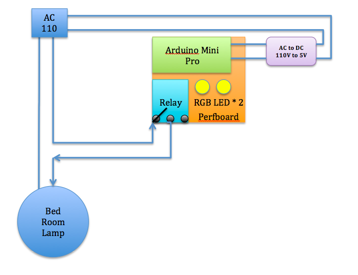
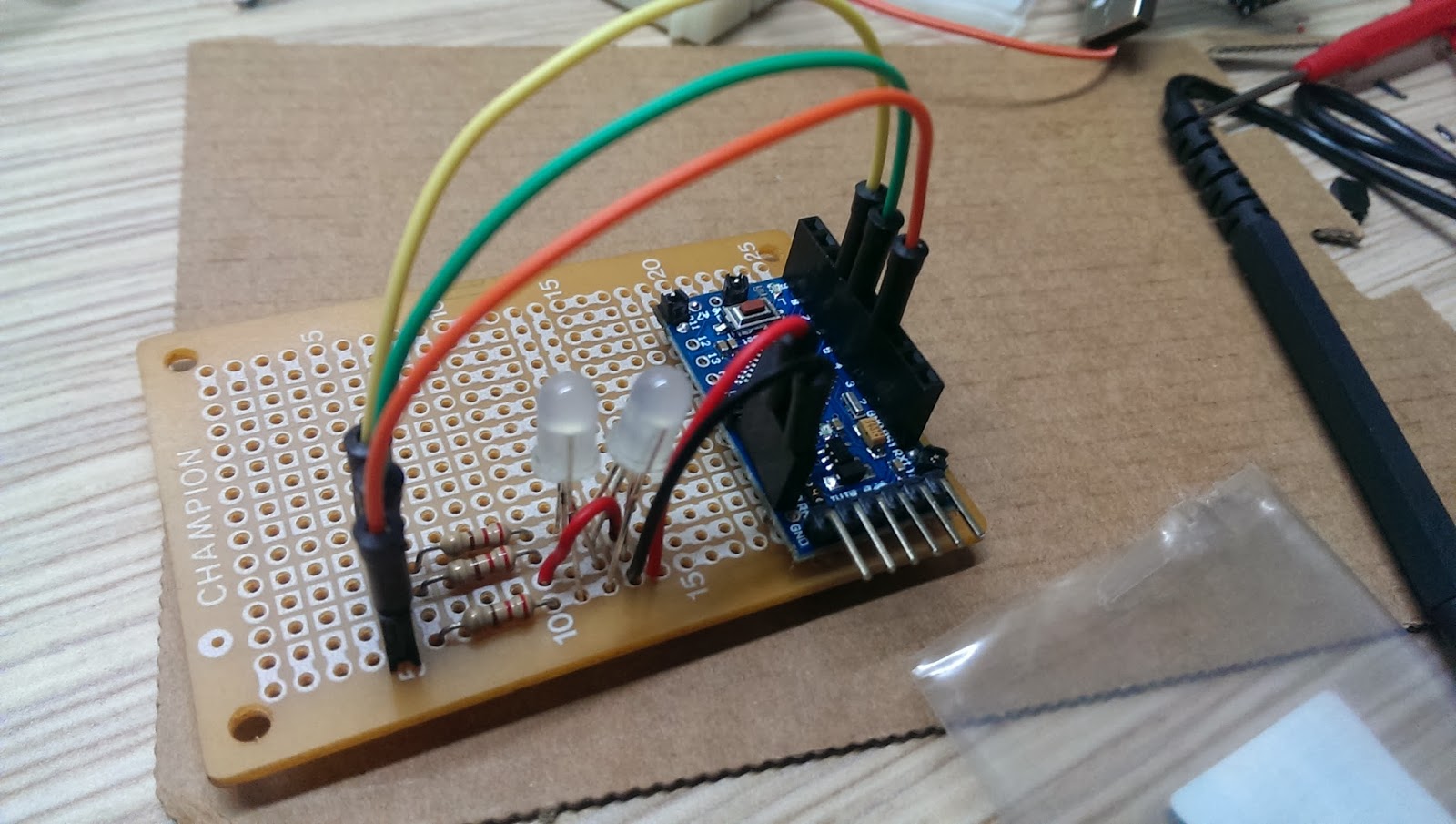
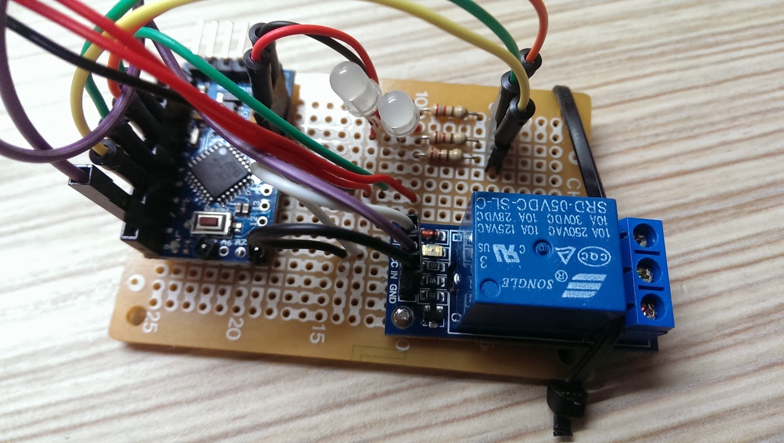
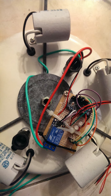
    This section of code is basically define relay pin numbers and status variables. See the comment in code that pin 13 is actually NodeMCU pin D7. You may see the NodeMCU ping mapping from this article.


    // Relay settings
    #define relay2Pin 13 //NodeMCU pin D7
    #define relay1Pin 15 //NodeMCU pin D8
    int relay1Status = 0; //switch of the relay; either 0=off or 1=on
    int relay2Status = 0; //switch of the relay; either 0=off or 1=on
    

    Section 2

    This section is the basic settings, from Wi-Fi SSID and password to your Adafruit.IO user names and AIO_KEY that I reminded you to make copy is needed here. Exchange all the information below with your own for this program to work.
    There are 4 items needs to be changed with your data:

    • WLAN_SSID
    • WLAN_PASS
    • AIO_USERNAME
    • AIO_KEY
    /***************************************************
      Adafruit MQTT Library ESP8266 Adafruit IO SSL/TLS example
      Must use the latest version of ESP8266 Arduino from:
        https://github.com/esp8266/Arduino
      Works great with Adafruit's Huzzah ESP board & Feather
      ----> https://www.adafruit.com/product/2471
      ----> https://www.adafruit.com/products/2821
      Adafruit invests time and resources providing this open source code,
      please support Adafruit and open-source hardware by purchasing
      products from Adafruit!
      Written by Tony DiCola for Adafruit Industries.
      SSL/TLS additions by Todd Treece for Adafruit Industries.
      MIT license, all text above must be included in any redistribution
     *****************************************/
    #include 
    #include "Adafruit_MQTT.h"
    #include "Adafruit_MQTT_Client.h"
    
    /************* WiFi Access Point *****************/
    
    #define WLAN_SSID       "Your_HOME_SSID"
    #define WLAN_PASS       "Your_HOME_SSID_PASSWORD"
    
    /************* Adafruit.io Setup *****************/
    
    #define AIO_SERVER      "io.adafruit.com"
    #define AIO_SERVERPORT  8883  // 8883 for MQTTS sercure, 1883 for non-Secure
    #define AIO_USERNAME    "stonez56"
    #define AIO_KEY         "4nnxxnnxxnnxxn88223"
    

    Section 3

    In Line 62, the code set up a subscription at Adafruit MQTT service Light 1 to get real time updated value.  "/feeds/light-1" is the subscription name and it must be the same with the one you defined at Adafruit "Feeds".

    In Line 63, it's reserved for future program extension to control RGB color light. 

    In Line 51, it's a MQTT publish feature that allows you to upload message from ESP8226 to Adafruit.IO MQTT server.  You might need it for other projects. 

    /************ Global State (you don't need to change this!) ******************/
    
    // WiFiFlientSecure for SSL/TLS support
    WiFiClientSecure client;
    
    //WiFiClient for non-secure
    //WiFiClient client;
    
    // Setup the MQTT client class by passing in the WiFi client and MQTT server and login details.
    Adafruit_MQTT_Client mqtt(&client, AIO_SERVER, AIO_SERVERPORT, AIO_USERNAME, AIO_KEY);
    
    // io.adafruit.com SHA1 fingerprint
    const char* fingerprint = "AD 4B 64 B3 67 40 B5 FC 0E 51 9B BD 25 E9 7F 88 B6 2A A3 5B";
    
    /****************************** Feeds ***************************************/
    
    // Setup a feed called 'test' for publishing.
    // Notice MQTT paths for AIO follow the form: /feeds/
    //Adafruit_MQTT_Publish light_color = Adafruit_MQTT_Publish(&mqtt, AIO_USERNAME "/feeds/light-color");
    //Adafruit_MQTT_Publish light_1 = Adafruit_MQTT_Publish(&mqtt, AIO_USERNAME "/feeds/light-1");
    
    /*************************** Sketch Code ************************************/
    // Bug workaround for Arduino 1.6.6, it seems to need a function declaration
    // for some reason (only affects ESP8266, likely an arduino-builder bug).
    void MQTT_connect();
    void verifyFingerprint();
    
    //set up a feed called 'light_1' / 'light_color' for subscribing to changes
    Adafruit_MQTT_Subscribe light_1 = Adafruit_MQTT_Subscribe(&mqtt, AIO_USERNAME "/feeds/light-1");
    Adafruit_MQTT_Subscribe light_color = Adafruit_MQTT_Subscribe(&mqtt, AIO_USERNAME "/feeds/light-color");


    Section 4

    This part is Arduino setup function. Basically, this setup Arduino serial monitor output and connect ESP8226 to your Wi-Fi network, as well as subscribe to MQTT services. 

    void setup() {
      Serial.begin(115200);
      delay(10);
    
      pinMode(relay1Pin, OUTPUT);
      pinMode(relay2Pin, OUTPUT);
    
      Serial.println(F("Home MQTT Light Control System"));
    
      // Connect to WiFi access point.
      Serial.println(); Serial.println();
      Serial.print("Connecting to ");
      Serial.println(WLAN_SSID);
    
      delay(1000);
    
      WiFi.begin(WLAN_SSID, WLAN_PASS);
      delay(2000);
    
      while (WiFi.status() != WL_CONNECTED) {
        delay(500);
        Serial.print(".");
      }
      Serial.println();
    
      Serial.println("WiFi connected");
      Serial.print("IP address: "); Serial.println(WiFi.localIP());
    
      // check the fingerprint of io.adafruit.com's SSL cert
      verifyFingerprint();
    
      //Subscribe to Adafruit Feed!
      mqtt.subscribe(&light_1);
      mqtt.subscribe(&light_color);
    
    }
    

    Section 5

    The Arduino loop keeps checking with Adafruit server to see if there were new messages. If there were new messages, then further check the subscription name. If the subscription name is equal to light-1, then check the light-1 feed_lastread content. If feed_lastread is ON or OFF then, the program call switchRelay function to either turn on light or turn off light. 

    This part also check the further project extension for color-light status.

    uint32_t x = 0;
    
    void loop() {
    
      String feed_lastread;
      // Ensure the connection to the MQTT server is alive (this will make the first
      // connection and automatically reconnect when disconnected).  See the MQTT_connect
      // function definition further below.
      MQTT_connect();
    
    
      Adafruit_MQTT_Subscribe *subscription;
      while ((subscription = mqtt.readSubscription(5000))) {
    
    
        if (subscription == &light_1) {
    
          Serial.print(F("Light-1:"));
          Serial.println((char *)light_1.lastread);
          feed_lastread = (char *)light_1.lastread;
          feed_lastread.trim(); //
          // Serial.println("Light 1:" + feed_lastread); //for verifying the varialble
          // *** NOTICE: adafruit.io publishes the data as strings, not numbers!!!
          if (feed_lastread == "ON") {
            switchRelay(2, 1);
          }
          if (feed_lastread == "OFF") {
            switchRelay(2, 0);
          }
        }
    
    
        if (subscription == &light_color) {
          Serial.print(F("Color-Light:"));
          Serial.println((char *)light_color.lastread);
          feed_lastread = (char *)light_color.lastread;
          feed_lastread.trim(); //
          // Serial.println("Color Light:" + feed_lastread); //for verifying the variable
          // *** NOTICE: adafruit.io publishes the data as strings, not numbers!!!
          if (feed_lastread == "ON") {
            switchRelay(1, 1);
          } else if (feed_lastread == "OFF") {
            switchRelay(1, 0);
          } else {
            colorLightFunction(feed_lastread.toInt());
          }
        }
      }
    

    Section 5

    This is the SwitchRealy function, it either turn off or turn on the relay module and print out the current status on Arduino serial monitor. 

    /* This turn on/off relay switch
    
    */
    void switchRelay(int relay, int stat) {
    
      if (relay == 2) { //this is light-1; 
        if (stat == 0) {
          digitalWrite(relay2Pin, LOW);
          Serial.println(F("Relay off"));
        }
        if (stat == 1) {
          digitalWrite(relay2Pin, HIGH);
          Serial.println(F("Relay on"));
        }
      }
      if (relay == 1) { //this is color-light; 
        if (stat == 0) {
          digitalWrite(relay1Pin, LOW);
          Serial.println(F("Relay off"));
        }
        if (stat == 1) {
          digitalWrite(relay1Pin, HIGH);
          Serial.println(F("Relay on"));
        }
      }
    }


    Section 6

    This part is all directly from Adafruit sample code. Just keep them here.

    void verifyFingerprint() {
    
      const char* host = AIO_SERVER;
    
      Serial.print("Connecting to ");
      Serial.println(host);
    
      if (! client.connect(host, AIO_SERVERPORT)) {
        Serial.println("Connection failed. Halting execution.");
        while (1);
      }
    
      //  if (client.verify(fingerprint, host)) {
      //    Serial.println("Connection secure.");
      //  } else {
      //    Serial.println("Connection insecure! Halting execution.");
      //    while(1);
      //  }
    
    }
    
    // Function to connect and reconnect as necessary to the MQTT server.
    // Should be called in the loop function and it will take care if connecting.
    void MQTT_connect() {
      int8_t ret;
    
      // Stop if already connected.
      if (mqtt.connected()) {
        return;
      }
    
      Serial.print("Connecting to MQTT... ");
    
      uint8_t retries = 30;
      while ((ret = mqtt.connect()) != 0) { // connect will return 0 for connected
        Serial.println(mqtt.connectErrorString(ret));
        Serial.println("Retrying MQTT connection in 5 seconds...");
        mqtt.disconnect();
        delay(5000);  // wait 5 seconds
        retries--;
        if (retries == 0) {
          // basically die and wait for WDT to reset me
          while (1);
        }
      }
    
      Serial.println("MQTT Connected!");
    }
    

    The end.

    2019/01/06

    Voice control with Google home and Arduino (2/3)

    Continue from Part 1

    This is the part 2 of the "Voice control with Arduino and Google Home Mini" tutorial. This section primarily explain how to setup the Adafruit MQTT and IFTTT related services.

    This is the demo of this tutorial:


    Step 1: Adafruit IO setup 

    Watch this video to see how I setup the Adafruit IO MQTT for this tutorial. This video has English Closed Captions, if you needed it.


    • If you would like learn more about MQTT, please visit Adafruit website to see it's great tutorials. Highly recommended for anyone not familiar with this technology to read. 

    AIO Key

    • AIO Key is your personal key that allows your Arduino ESP8226 to talk to Adafruit IO MQTT server. Keep it safe and not to share with others. 
    • Log in to your account and Click "AIO Key" on the left menu.
    • Write down the AIO Key (You will need this in Arduino to connect to Adafruit) See below:
    • Click on the "View AIO Key" button to see your AIO Key (shown below)


    Write down the AIO Key for Arduino ESP2886 coding use later. 

    Step 2: Setup IFTTT Applet

    • IFTTT is stands of "If This Than That". If you were not familiar with IFTTT, you could checkout more information from these resources:
      1. What's IFTTT?
      2. How to setup IFTTT?
    • Here is how I setup my IFTTT Applet for this tutorial. This video has English Closed Captions, if you needed it.

    Step 3: Check Adafruit and IFTTT setup

    • Turn on Google Home Mini and say "Turn on light one".
    • Install IFTTT App on your smartphone, if you used a smartphone rather than a Google Home.
    • Google assistant should reply "Sure, light one on".
    • From the Adafruit feeds page, you should see the data showing up there immediately reflecting the message you sent; in red square below.
    • Then, your setup is successful!

    The 2nd part is completed. In the next section, I will show you all the physical setup and the Arduino codes to make this project work.


    Troubleshooting:


    Until then, see you next time!

    Continue to read: Part 3 Arduino 程式解說 (coming soon)


    2019/01/01

    Voice control with Google Home and Arduino (1/3)

    Preface

    After received my Google Home Mini from Walmart, my family and I are really enjoyed and satisfied with the voice features and sound quality. Voice control lighting is always on my Arduino DIY list. After I received all the components, I went ahead and made this project during my X'mas holiday. The Google Home Mini I bought came with a Chromecast in a Smart TV kit package at price of USD$45 during holiday sales. What a bargain! 

    * Photo from Walmart

    Here are the URL links about this tutorial, totaling 3 sections:


    Goal

    Simply say "Ok Google, turn Light One On or Off" to Google Home Mini and it does the job!  I intended to add "One" there, so I might have the 2nd or 3rd lights that I could control in...hope not in the distant future. :)

    See the demo below:


    How does it work?

    Programming Steps to show you the working flow

    1. Your voice command send to IFTTT through Google Home Mini 
    2. IFTTT Applets engage Google assistance service and inteprete the voice command into text and send to Adfruit.IO MQTT service
    3. MQTT service received the message(from Google home to IFTTT) and based on the Adafruit "Feeds" setting to store the received message on the MQTT server.
    4. Adruino ESP8266 at home was programmed to subscribe new message from Adafruit. As soon as the Adafruit MQTT server has updated message, Adafruit server push the message back to Arduino ESP8226.
    5. ESP8226 recevie the message and act accordingly to either trigger the relay module.
    6. If the messae is "ON" then, ESP8226 turn on light by swith relay module on. Otherwise, the message is "OFF", then trun off light by swith relay module off.

    !!EXTRA CAUTION!!

    SAFETY is first priority! This project involves 110V AC which it is quite dangerous if not handled carefully! Please turn the main power source off before all the AC related connections. Double and triple check for short and correct connections before turn back on AC! I'm just to show you how I made this project and not responsible for anything happened to you or your family and properties in case if there is an accident. 

    Components Needed

    • NODEMCU ESP8226 * 1
    • 10A 110v/250v AC Relay * 1
    • Wall plug outlet * 1
    • Wires for Arduino connection * 4 or 5
    • Wires for Wall plug connection * 3

    Schematic 

    I drew this illustration below to show you how did I connected all components together.


    Connections:

    • ESP8226 D7 to Relay IN
    • ESP8226 GDN to Relay GDN
    • ESP8226 3.3V to Relay VCC
    • Relay NC(Normally Close) to AC Plug outlet top end (refer to above illustration)
    • Relay C(Common) to AC 110V 
    • AC Plug outlet bottom end to AC 110V GND
    • AC Plug ground (not used in this project, my old house does not have this)
    That's all for this section. Next time, I will show you how to setup Adafruit and IFTTT. They are the most important parts of this project. Until next time, see you!

    Please Continue to read: Setting software - Part 2 of this tutorial 

    2018/02/27

    Arduino - Switch celling light with TV remote (2/2)

    This is the part two of Switch celling light with TV remote tutorial. If needed, please check out the part one from link below. By the way, the source code is also available there.


    Quick Link


    System Design

    See the illustration below. I used a phone charger(purple block; AC110V to DC5V) to supply power from 110v AC power outlet from the celling. The Arduino controls the relay module to switch the celling light and Arduino interpret IR code to change  RGB LED to shift color and on/off accordingly. 

    Connections

    • IR Receiver to Arduino pin 2
    • IR Receiver + to VCC
    • IR Receiver - to GND
    • Relay + to VCC
    • Relay - to GND
    • Relay to Arduino pin 8
    • RGB Red to Resistor to Arduino pin 3
    • RGB Green to Resistor to Arduino pin 5
    • RGB Blue to Resistor to Arduino pin 6
    • *** CAUTION: Turn off home main power switch first before 110V connection! ***
    • *** Connect 110V to the system after you secure prefboard to the celling light ***
    • Connect 110V VCC to "Relay NO (Normally Open)" on the left
    • Connect Relay COM (Common connection) to 110V GND. 

        Step by step


        Solder pins to Arduino mini pro.

        Pick up the corner of the perfboard as the fix position. Then, solder pin header connectors on the side of Arduino mini pro, so we could have the flexibility to change wiring later.  Don't forget to face Arduino five data pins towards outside of the prefboard for easier connection to upload source code later.

        Selected few unused solder holes from the Arduino Mini Pro and used the connection pin headers as supporting material on the perfboard. This could prevent unintentional shortage. See below:


        After fixed Arduino Mini Pro in place, solder RGB LED, resistors, and wires to the prefboard. 
        Remember to power up to test the whole setup before moving forward.


        I used a screw to fix the relay module on the perfboard. However, fixed on one side is not stable enough, so I took a cable tight to keep the relay module tightly in place.  *Remember to reserve a very long IR reception wire*, so the IR receiver could placed outside of the celling light or the IR receiver might be obscured by the decorative glass cover.


        Here is the over all system in action!


        Next, find a good power source for the system. 
        For this project, I used a HTC smart phone charger. At least, HTC is (or was?) an international brand name smartphone company and has good reputation regarding to safety. Again, for safety reason, please use certified chargers only, such as CE, FCC, UL from well-know brand name company. *** Do not use no brand or very cheap chargers from unknown source. You are on your own risk! ***


        I used a short USB cable to connect the HTC charger to the system.  Cut the USB cable near micro-B (smaller connector) and strip the shielding off the cable. In there, you will find four wires with GREEN, WHITE, RED, BLACK. Solder the RED(5V+) and BLACK(GND) wires to positive and negative respectively on the perfboard. 

        Cable connection:
        • USB type-A (Larger connector) to HTC charger
        • USB micro-B (smaller connector) to system


        After soldered the USB wires, plug the charger to power outlet and test the system.


        My bedroom celling light looks like this below. It has a switch located at the entrance of the bedroom. And the switch works like this. After implement this system, the control of the switch will be shift to Arduino Mini Pro.

        For every switch on/off, it cycles through 

        1.  Turn on three lights
        2.  Turn off
        3.  Turn on Five lights
        4.  Turn off 
        5.  Turn on two lights
        6.  Turn off


        Carefully loosen the screw from the bottom glass cover and remove the decorative glass away.


        Drill a hole on the light base for tightening the system.


        Use a screw to secure the prefboard to the celling light as shown below.


        *** Important: Wrong connection will cause the light not working ***
        • Connect 110v VCC to "Relay NO (Normally Open)" on the left
        • Connect Relay COM (Common connection) to 110v GND


        When connect AC 110V power line to phone charger, please make sure the isolation is done properly. It would be better to use Heat shrink tube for the isolation. However, I didn't have those on hand, so I used the isolation tape and tight them 3~4 times to ensure it's 100% isolated.  

        *** Disclaimer: Many experts expressed safety concerns for connecting Arduino with relay to AC 110V power!  I'm not responsible for any damage or lose that could happened to your projects or properties! You are at your own risk of doing this! ***


        Before tighten the light frame and decorative glass back to the celling, use the remote to test the system to see if it's working as expected.

        See the red circle below, that's the IR receiver that I used an extended wire from the perfboard to the rim of the light to get better IR reception.


        Let's try to change the color with the TV remote.


        Finally, the project is completed! Watch the video below to see it in action!
        Now I can turn the celling light off directly from my bed after turn TV off!  


        This is the end of this tutorial. I hope you liked it! Please leave comments below and I will see you next time.

        Enjoy!


        2018/02/25

        Arduino - Switch celling light with TV remote (1/2)

         Preface

        It must be happened to you before that in a very cold night watching TV or movie in bed and you were ready for bed. You turned off the TV or DVD player with remote control easily. However, for the celling light, you just had to get out of the bed to turn the light off. What a pain! 

        After I searched the Internet, there are many examples out there suit for this purpose, such as IR receiver, relay module, and RGB LED shift hue and most of them have codes that I could utilize on this project.  

        Quick Link

        Material Needed

        • Arduino mini pro *1 
        • USB upload module *1 
        • Relay module (5V/10A/125V) * 1 
        • IR Receiver LED * 1 (Aixin AX-1838HS 38KHz * 1 / All 38KHz should work) 
        • RGB LED *2 
        • Resister 220 Om * 3
        • Few jump wires
        • Any TV or DVD remote you have at home
        • Breadboard * 1
        It's not difficult to find these components on Amazon or eBay.

        System Functionality

        Assign two buttons on the remote to control the celling light. Remember to assign less frequently used buttons on the remote or you might accidentally activate the particular function on your appliances. :)
        • Button 1: Turn on/off
        • Button 2: Switch LED color hues (static or color shifting)

        Schematic

        This schematic is made with Fritzing. 
        You can download it from its official website: www.fritzing.org


        Connections

        • IR Receiver to Arduino pin 2
        • IR Receiver + to VCC
        • IR Receiver - to GND
        • Relay + to VCC
        • Relay - to GND
        • Relay to Arduino pin 8
        • RGB Red to Resistor to Arduino pin 3
        • RGB Green to Resistor to Arduino pin 5
        • RGB Blue to Resistor to Arduino pin 6

        Check Remote IR code

        You have to find out the remote button IR codes on your remotes and embed them in the source code below for this project to work.


        For Example, my Sanyo TV remote has the following codes. As you can see, I have assigned two buttons for each feature to have a fall back plan.

        • Celling Light Switch function
          • Mute:irCode: 1CE318E7,  bits: 32  sanyoLight1
          • Channel minus :irCode: 1CE3D02F,  bits: 32  sanyoLight2
        • LED Switch function
          • Volume minus :irCode: 1CE3F00F,  bits: 32  sanyoLED1
          • CH View: irCode: 1CE352AD,  bits: 32 sanyoLED2

        To find out the IR codes for you remote, please refer to my previous IR Repeater Tutorial (Part 2)

        Source Code

        /*
         * Author: Stonez56
         * IRRemote for bedroom lighting control 
         *   Light buttons: Switch lights through the 
         *            cycle - 3, 5, 2, off with 2 types of remote
         *   LED buttons: Switch display random color a, b, transistion, off
         */
        
        #include <IRremote.h>
        
        // Setting up pins
        // Setup pin 8 for relay. 
        //    For some reason, Pin 13 will cause relay to switch one time
        //    when system powers on
        const int relay1Pin = 8; 
        const int redPin = 3;                    
        const int greenPin = 5;
        const int bluePin = 6;
        const int irReceiverPin = 2;
        
        // Milisecond to delay when shifting colors
        int colorShiftTime[] = {20, 10, 1, 50}; 
        int colorShiftTimeCounter = 0;
        
        int myPins[] = {2, 4, 8, 3, 6};
        int LEDstatus = 0;       // mode of LED or switch light
                            /*
                             * 0 = LED off
                             * 1 = LED orange
                             * 2 = LED color rotation
                             * 3 = Relay Light swtich
                             */
        
        int relay1Status = 0; // Switch of the relay; either 1 or 0;
        
        
        IRrecv irrecv(irReceiverPin);            
        decode_results results;  // IR decode_results 
        
        unsigned int rgbColour[3]; //RGB LED array
        
        unsigned int preCode = 0x0;  //Previous remote code
        unsigned int currentCode = 0x0; //Current remote code
        
        /* Define remote codes  
        Remote A (iBit Remote)
         Switch
          - (L/R) irCode: 609E09F6,  bits: 32 bitLigth1
          - Subtitle:irCode: 609E8877,  bits: 32  bitLight2
         LED Switch
          - Sound change irCode: 609E42BD,  bits: 32 bitLED1
          - Favorite channel:irCode: 609E728D,  bits: 32 bitLED2
          LED Color speed 
            - colorShiftTime: irCode: 
        
        */
         
        const unsigned long bitLight1 = 0x609E09F6;
        const unsigned long bitLight2 = 0x609E8877;
        const unsigned long bitLED1 = 0x609E42BD;
        const unsigned long bitLED2 = 0x609E728D; 
        const unsigned long bitLEDspeed = 0x609EAA55;
        /*
        Remote B (Sanyo Remote)
         Switch
          - Mute:irCode: 1CE318E7,  bits: 32  sanyoLight1
          - Channel minus :irCode: 1CE3D02F,  bits: 32  sanyoLight2
         LED Switch
          - Volume minus :irCode: 1CE3F00F,  bits: 32  sanyoLED1
          - CH View: irCode: 1CE352AD,  bits: 32 sanyoLED2
          LED Color speed
            - colorShiftTime: irCode: 
        
        */
        const unsigned long sanyoLight1 = 0x1CE318E7;
        const unsigned long sanyoLight2 = 0x1CE3F00F;
        const unsigned long sanyoLED1 = 0x1CE352AD;
        const unsigned long sanyoLED2 = 0x1CE3D02F;
        const unsigned long sanyoLEDspeed = 0x1CE350AF;
        
        void setup()
        {
          
          //////Serial.begin(9600);   
          irrecv.enableIRIn(); // enable IR pin
          pinMode(relay1Pin, OUTPUT);
          // Start off with the LED off.
          ledOff();
        }
        
        // Turn off LED
        void ledOff(){
          rgbColour[0] = 255;
          rgbColour[1] = 255;
          rgbColour[2] = 255;  
          setColourRgb(rgbColour[0], rgbColour[1], rgbColour[2]);
        
          preCode = currentCode;
          while(preCode == currentCode){
                currentCode = checkRemoteCode();
                // Check the code on Serial port
                Serial.print(rgbColour[0]); Serial.print(" | ");
                Serial.print(rgbColour[1]);  Serial.print(" | ");
                Serial.println(rgbColour[2]);
          }
        }
        
        /*
        * Turn on LED to Orange color
        */
        void ledOrange(){
          //LED color orange??
          rgbColour[0] = 65391;
          rgbColour[1] = 400;
          rgbColour[2] = 255;  
          setColourRgb(rgbColour[0], rgbColour[1], rgbColour[2]);
        
          preCode = currentCode;
          while(preCode == currentCode){
                currentCode = checkRemoteCode();
          }
        
        }
        
        
        /*
         * Rotating RGB LED color
         */
        void colorRotation(){
          // Start off with red.
          rgbColour[0] = 0;
          rgbColour[1] = 255;
          rgbColour[2] = 255;  
        
          preCode = currentCode;
         
          // Choose the colours to increment and decrement.
          for (int decColour = 0; decColour < 3; decColour += 1) {
            int incColour = decColour == 2 ? 0 : decColour + 1;
         
            // cross-fade the two colours.
            for(int i = 0; i < 255; i += 1) {
              rgbColour[decColour] -= 1;
              rgbColour[incColour] += 1;   
        
              setColourRgb(rgbColour[0], rgbColour[1], rgbColour[2]);
              delay(colorShiftTime[colorShiftTimeCounter]);
              currentCode = checkRemoteCode();
        
        /*
              Serial.print(" R:");Serial.print(rgbColour[0]);
              Serial.print(" G:");Serial.print(rgbColour[1]);
              Serial.print(" B: ");Serial.println(rgbColour[2]); 
              */     
              //if accepted new remote codes,
              //     exit this function and back to the main loop;
              if(preCode != currentCode){
                return;
              }
            }
          }
        } // End of LED color rotation
        
        
        /* This turn on/off relay switch
         *
         */
        void switchRelay(){
          relay1Status = 1 - relay1Status;   
           if(relay1Status == 0){
            digitalWrite(relay1Pin, HIGH);
            delay(500);
           }else{ 
            digitalWrite(relay1Pin, LOW);
            delay(500);
           }
        }
        
        /* Check remote code and return a mode to be changed
         *
         */
        int checkRemoteCode(){
          if (irrecv.decode(&results)) { // Received IR code and decoded ok!
            // Print to Serial port for debug purposes
            Serial.print("Color shift time: ");
            Serial.print(colorShiftTime[colorShiftTimeCounter]);
            Serial.print("  irCode: ");           
            Serial.print(results.value, HEX);    // IR decode
            Serial.print(",  bits: ");          
            Serial.println(results.bits);        // IR codes
            
            irrecv.resume();                    // Continue to receive next IR code 
            if(results.bits == 32){ //only 32bit code will be evaluated
              switch(results.value){
                /*All these buttons switch lights */ 
                case bitLight1:
                case bitLight2:
                case sanyoLight1:
                case sanyoLight2:  
                case 0x992A2843: //Benq Remote Green button for test
                     LEDstatus = 3; //switch relay;
        
                  break;
                case bitLED1:
                case bitLED2:
                case sanyoLED1:
                case sanyoLED2:
                      //Check LEDstatus and switch to next mode
                      LEDstatus += 1;
                      if(LEDstatus >= 3){ 
                          LEDstatus = 0; //LEDstatus only has 0,1,2 if == 3, reset it to 0;
                      }
                  break; 
                case bitLEDspeed:
                case sanyoLEDspeed:
                      colorShiftTimeCounter++;
                      if(colorShiftTimeCounter==4){ 
                          colorShiftTimeCounter=1; //only 4 elements, from 0~3
                        }
                      colorShiftTime[colorShiftTimeCounter];
                  break;
                default:
                  break;        
              } //switch
            } // check 32bits
          } //end of get a remote code
        
          return LEDstatus;
        }
        
        void setColourRgb(unsigned int red, unsigned int green, unsigned int blue) {
          analogWrite(redPin, red);
          analogWrite(greenPin, green);
          analogWrite(bluePin, blue);
         }
        
        void loop(){
          switch(LEDstatus){
             case 0:
                ledOff();
                break;
             case 1:
                ledOrange();
                break;
             case 2:
                colorRotation();
                break;
             case 3:
                switchRelay();
                LEDstatus = 99;
                break;
             default: // set it up to do nothing, but wait the remote code to activate
                 break;
          }
          //constanly check new remote code
          LEDstatus = checkRemoteCode();
          //////Serial.print("LEDstatus: ");Serial.println(LEDstatus);
        } // end of loop
        
        
        Here is the prototype in the photo below.


        In next tutorial, I will show you the 2nd phase to put everything together and install the whole system in the celling light.  See you soon!