Posts

Showing posts from September, 2017

Weekend Project – Arduino Temperature Meter V2

Image
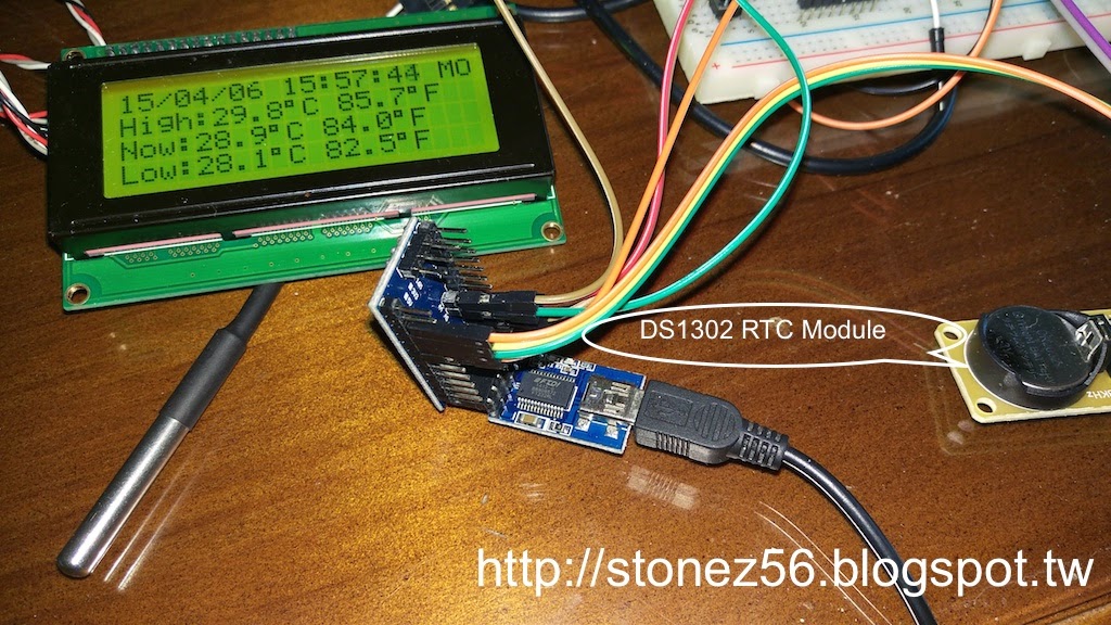
In the last tutorial, I have shown how to make a Temperature Meter which records highest, current, and lowest temperature with Arduino Mini Pro and a DS18B20 temperature probe. One of the readers suggested me if I could record the highest and lowest temperatures measured into EEEPROM, then I won't lost the highest/lowest temperature once power is down. It's a good idea, but  I thought, it would be a greater idea if I kept both time stamp and high/low temperatures! (Writing data to EEEPROM tutorial would be in V3....unfortunately...)  So, I searched Arduino.cc website and found abundant information about DS1302/DS1307 RTC clock modules. Many people mentioned in forums that DS1302/DS1307 are not very precise and tend to draft of few seconds per week/month. However, DS1302 is quite affordable, so I bought 2 pieces from an auction sites and to give it a try.  Reference DS1302RTC data at Arduino.cc Functions added in Temperature V2: Display date/time clock and date of w

Testing Arduino POV (Persistent of Vision) | 試試 Arduino POV (視覺暫留)

Image
I have been attracted to Arduino POV [1] for quite a while, but I didn't have a chance to actually make it myself.   Luckily, I found this easy to follow Arduino POV tutorial [2] on Instructable.com and within an hour, my son and me made two Arduino POV sets and have fun for the entire afternoon. Material needed for this tutorial: Arduino Nano * 1 (All other kinds of Arduino board will do) LED * 7 220 resistor * 7  Jump wire ~ up to 10 (female to male) Prefboard * 1  Battery pack (If you would like have fun without tethered with USB) Easy Wire Connection as follow: LED1 ~ LED7 negative pin to Prefboard GND Prefboard to Nano(or Uno) GND pin LED1 ~ LED7 postive pin to Nano(or Uno) D2 ~ D8 pin USB power to Nano USB port to supply power (or use a battery back to supply power) Schematic: (I use www.tinkercad.com to draw this schematic below, just in case you interested.) This is a fun a easy project! First, just connect LED cathode(negative) and resist

Test PIR Sensor with Arduino | PIR 感應器

Image
In this tutorial, I would like to show you how to make a PIR sensor to work with Arduino.  PIR stands for Passive Infrared sensor. What it does is to measure infrared (IR) light radiating from objects in its field of view. A frequently use case is installing a PIR sensor at the hall way and whenever PIR sensor detects people walk towards the hall way, then the PIR sensor turn on the light.   Please refer to Wikipedia for more information about PIR . Material needed for this tutorial: Arduino Nano * 1 (All other kinds of Arduino board will do) PIR sensor * 1 Buzzer * 1 LED * 1 (You may just utilize the LED on Arduino Nano) 220 resistor * 1 (No need you use the LED on Arduino Nano) Jump wire ~ up to 10 (female to female) Wire Connection as follow: PIR Ground pin to Nano(or Uno) GND pin PIR Power pin to Nano +5V pin PIR data pin to Nano D2 pin LED ground to Nano GND pin LED power pin to 220K resistor pin 220K resistor pin to Nano pin 13 Buzzer postive pin to Nano