Android control color RGB LED using HC-05 Bluetooth with Arduino (Part I)
Android control color RGB LED using HC-05 Bluetooth with Arduino (Part I)
Part II of this tutorial is here!
Updated Sketch for ESP32 boards https://stonez56.blogspot.com/2021/07/android-control-color-rgb-led-with.html
This time, I am going to show you how to use Android phone to connect to HC-05 Bluetooth module and Arduino.
Hardware needed:
- Arduino mini pro * 1
- HC-05 Bluetooth module * 1
- RGB LED * 2
- Jump wires * 10
HC-05 Bluetooth Module wiring as follow:
- TX connect to Arduino Pin 11(RX)
- RX connect to Arduino Pin 12(TX)
- Remember to connect TX on the HC-05 to RX on the Arduino and RX on the HC-05 to TX on the Arduino, so Arduino can receive data correctly.
- VCC connect to 5V power
- GND connect to Ground
RGB LED wiring as follow:
Warning: You must connect Arduino mini pro, so your PWM Pin can control LED’s color! For example, Arduino mini pro only has 6 PWM pins and they are 3, 5, 6, 9, 10, and 11, other pins do not have PWM.Refer to Wikipedia for PWM
- R connect to Arduino Pin 3
- Common Anode connect to 5V
Note: if you bought common anode LED, then this pin must connect to VCC 5V. If you bought common cathode LED, then this pin must connect to GND - G connect to Arduino Pin 5
- B connect to Arduino Pin 6
Arduino wiring as follow:
- GND connect to Ground
- VCC connect to 5V

If you connect all the parts together, it will look like this:

The completed Arduino code is listed here:
#include <Softwareserial.h>
#include <Wire.h>//Include libraries: SoftwareSerial & Wire
SoftwareSerial BT(11,12); //Define PIN11 & PIN12 as RX and TX pins

//RGB LED Pins
int PIN_RED = 3;
int PIN_GREEN = 5;
int PIN_BLUE = 6;
//RED LED at Pin 13
int RED_LED = 13;
String RGB = ""; //store RGB code from BT
String RGB_Previous = "255.255.255)"; //preserve previous RGB color for LED switch on/off, default White
String ON = "ON"; //Check if ON command is received
String OFF = "OFF"; //Check if OFF command is received
boolean RGB_Completed = false;

void setup() {
  Serial.begin(9600); //Arduino serial port baud rate:9600
  BT.begin(9600);//My HC-05 module default baud rate is 9600
  RGB.reserve(30);

  pinMode(RED_LED, OUTPUT);
  //Set pin13 as output for LED,
  // this LED is on Arduino mini pro, not the RGB LED
}

void loop() {
  // put your main code here, to run repeatedly:

  //Read each character from Serial Port(Bluetooth)
  while(BT.available()){
    char ReadChar = (char)BT.read();

    // Right parentheses ) indicates complet of the string
    if(ReadChar == ')'){
      RGB_Completed = true;
    }else{
       RGB += ReadChar;
    }
  }

  //When a command code is received completely with ')' ending character
  if(RGB_Completed){
   //Print out debug info at Serial output window
      Serial.print("RGB:");
      Serial.print(RGB);
      Serial.print("     PreRGB:");
      Serial.println(RGB_Previous);

      if(RGB==ON){
          digitalWrite(13,HIGH);
          RGB = RGB_Previous; //We only receive 'ON', so get previous RGB color back to turn LED on
          Light_RGB_LED();

      }else if(RGB==OFF){
          digitalWrite(13,LOW);
          RGB = "0.0.0)"; //Send OFF string to turn light off
          Light_RGB_LED();
      }else{
          //Turn the color according the color code from Bluetooth Serial Port
          Light_RGB_LED();
          RGB_Previous = RGB;
      }
      //Reset RGB String

      RGB = "";
      RGB_Completed = false;


  } //end if of check if RGB completed

} // end of loop

void Light_RGB_LED(){

  int SP1 = RGB.indexOf('.');
  int SP2 = RGB.indexOf('.', SP1+1);
  int SP3 = RGB.indexOf('.', SP2+1);
  String R = RGB.substring(0, SP1);
  String G = RGB.substring(SP1+1, SP2);
  String B = RGB.substring(SP2+1, SP3);

  //Print out debug info at Serial output window
  Serial.print("R=");
  Serial.println( constrain(R.toInt(),0,255));
  Serial.print("G=");
  Serial.println(constrain(G.toInt(),0,255));
  Serial.print("B=");
  Serial.println( constrain(B.toInt(),0,255));
  //Light up the LED with color code

//**2014-09-21
//Because these RGB LED are common anode (Common positive)
//So we need to take 255 to minus R,G,B value to get correct RGB color code
  analogWrite(PIN_RED,  (255-R.toInt()));
  analogWrite(PIN_GREEN, (255-G.toInt()));
  analogWrite(PIN_BLUE,  (255-B.toInt()));

}
You need to go to Google Play Store and download "BT LED Controller"; you need to use it with this tutorial. You may download APP here
This is what Android BT LED Controller App can do:
1. Connect to Bluetooth2. Wireless control LED on/off
3. Wireless control LED to change the color
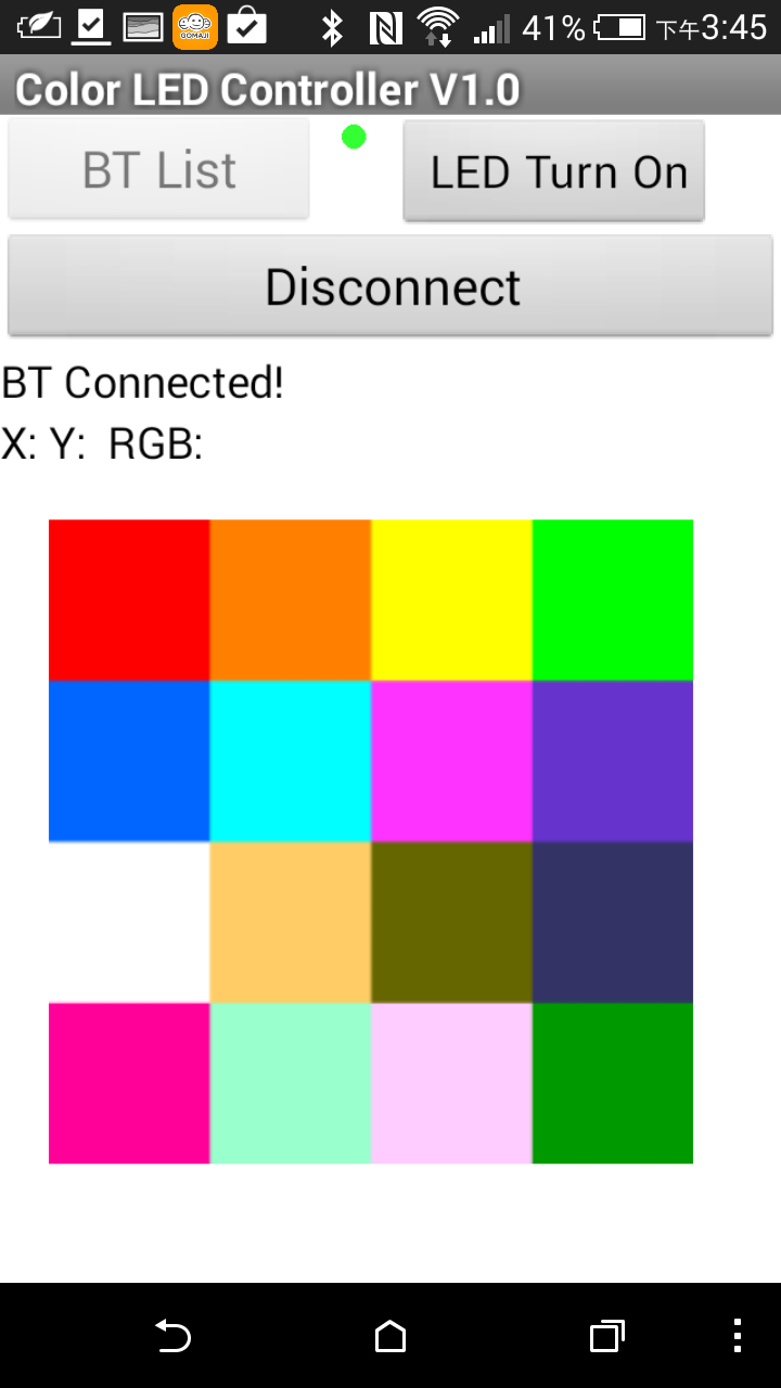
The screen of Android APP is below and you can use it easily:
- Click the ”BT-List” button (The red dot next to it means BT not connected)

- Next select the Bluetooth you want to connect from the list, after it connected successfully, the APP will jump back to the main screen

- On the main screen says BT connected (The green dot indicates BT connected)
- Click LED on / LED off button, you can turn LED on/off

- Click any color block on the App, the RGB color code will be sent to HC-05 and HC-05 will send the RGB color code to Arduino. RGB code is composed 3 numbers of 1~255 with “)” as the ending character, such as “255.20.10)”. Arduino receives a character at a time from the serial port and it combines all characters together. When a “)” is received, the RGB code is completed.
- Arduino then decompose RGB code string into 3 sets of numbers for R, G, B, and then send the code to RGB LED to display the color indicated.
- As shown below (RGB code 255.51.255 will make RGB LED to show magenta)
- Click Disconnect to cut the connection between Android and Arduino.

You also learn how to use this APP by watching
the video below:
Android 藍芽連線控制彩色 RGB LED (Part I)
本次教學將如何用 Android 程式以藍芽方式連線到HC-05藍芽模組及Arduino.
硬體所需材料:
- Arduino mini pro * 1
- HC-05 Bluetooth module * 1
- RGB LED * 2
- Jump wires * 10
HC-05 Module 接法:
- TX接到 Arduino Pin 11 (RX)
- RX接到 Arduino Pin 12 (TX)
就是發射端與接收端要反接到Arduino, 這樣 Arduino 才收的到訊號 - VCC 接 5V 電源
- GND 接地
RGB LED 接法:
注意: 一定要接 Arduino mini pro 有 PWM 的腳位才能控制LED的顏色!
以 Arduino mini pro PWM 腳位只有 : 3, 5, 6, 9, 10, and 11,其它沒有 PWM.
- R 接 Arduino Pin 3
- Common Anode 接 5V
(我買的是共陽的 LED, 所以這支腳要接 5V,若你買的是共陰的 Cathode, 則要接 GND) - G 接 Arduino Pin 5
- B 接 Arduino Pin 6
Arduino 接法:
- GND 接地
- VCC 接 5V
Arduino, HC-05 module, & RGB LED 電路圖如下:
我把這些材料通通接好如下:
請由 Google Play Store 下載 BT_LED_Controller V1.0 與這個程式搭配這個教學使用.
由此下載 APP
Android BT_LED_Controller V1.0 有下列功能:
- 藍芽連線
- 無線遙控 LED 開/關
- 無線遙控 LED 改變它的顏色
Android App 畫面如下,使用方法很簡單:
- 點選上方 "BT-LIST" 鈕 (右方的小紅點表示藍芽尚未連線)


- 主畫面上顯示 BT Connected (小綠點表示已藍芽連線成功)
- 按下 LED Turn on / LED Turn Off 可以打開/關閉 LED
- 點選 App 上的任一顏色方塊,App 會把那個方塊的 RGB code 送到 HC-05,再由 HC-05傳給 Arduino, RGB code 由3組 1~255的數字組成, 再加上右括號尚作是結束符號, 如 255.20.10), 當 Arduino 由 serial port 一個字元一個字元接收, 一直收到 ) 時,才當作是一個完整的 RGB code。
- Arduino 把 RGB code 字串解析後,再送給 RGB LED 顯示指定的顏色
如下圖 (RGB code: 255.51.255 會傳到到 Arduino 顯示出紫紅色) - 點選 Disconnect 則關閉 Android 和 Arduino 的連線
- 完成測試

請參考底下的影片顯示操作的方法:

Cool project, is the source for you Android application posted somewhere?
ReplyDeleteI have posted Android source code in App Inventor II format.
DeleteIf you want, you may download the App from Google Play market
http://stonez56.blogspot.tw/2015/02/arduino-project-android-control-color.html
Hi! Can you do an app like this but sending the colour info in a hex string, for RGBW and time?
ReplyDeleteRRRRGGGGBBBBWWWWTTTT
Like 00 00 00 00 00 00 00 00 00 00
Hi Melkor,
DeleteDo you mean pass colour code in Hex code? It should be okay. However, I understand what's RRRR GGGG BBBB, but what's WWWW and TTTT stands for?
Hi, Stonez
ReplyDelete謝謝您的文章。
因想加入一開關於電路中,控制Pin_BLUE亮暗。修改程式如下:
void loop() {
buttonState = digitalRead(buttonPin);
if (buttonState == HIGH) {
digitalWrite(PIN_BLUE, HIGH);
}
else {
digitalWrite(PIN_BLUE, LOW);
}
實驗後發現藍牙無法同時控制Pin_BLUE狀態...
想請教您,該如何修改較好?
還請給予指教。
PIN_BLUE is part of the RGB LED pin, so you should try to give PIN_BLUE value 0 with analogWrite to simulate the pin is off.
DeleteSome thing like this:
buttonState == HIGH, then analogWrite(PIN_BLUE, 255);
buttonState == LOW, then analogWrite(PIN_BLUE, 0);
I haven't tested this myself, so please give it a try and let me know if it works.
Stonez
Hi, Stonez
Delete感謝您的回覆!
經過測試,Pin_BLUE依然是on/off狀態,無法再隨藍芽控制...
(我的想法是:開關按下後,Pin_BLUE先亮。藍牙Turn On後,再依藍牙給的數值改變顏色)
你是用RGB LED嗎? 一開機時要先亮藍色?
DeleteHi, Stonez
Delete是RGB LED沒錯。先亮藍色只是方便辨識而已,並無特定。
後續我修改的一部份的碼,還是有些問題:
String RGB_Previous = "0.0.255)"
void loop() {
val = digitalRead(buttonPin);
if (val == 1) {
digitalWrite(13,HIGH);
RGB = RGB_Previous;
Light_RGB_LED();
}
else {
RGB = "0.0.0)"
Light_RGB_LED();
結果還是不行...
不知您是否方便指導一下?
請先注意下列事項,先確定都有依照做
Delete1) RGB LED 接法:
注意: 一定要接 Arduino mini pro 有 PWM 的腳位才能控制LED的顏色!
以 Arduino mini pro PWM 腳位只有 : 3, 5, 6, 9, 10, and 11,其它沒有 PWM.
2) 是你用內建的 Pin 13嗎? 那個 pin 腳有內建一個 紅色LED,不能變色。
3) 你要用 analogWrite(PIN_BLUE, 255),不是 digitalWrite
4) Common Anode 接 5V (我買的是共陽的 LED, 所以這支腳要接 5V,若你買的是共陰的 Cathode, 則要接 GND)
5) Because these RGB LED are common anode (Common positive),
//So we need to take 255 to minus R,G,B value to get correct RGB color
analogWrite(PIN_BLUE, (255-B.toInt()));
Hi, Stonez
Delete是的,我是參考您的接法,並採用共陽RGB LED。
Pin 13主要是判別有無動作,有試過將該行拿掉,沒有影響。
修改成analogWrite(PIN_BLUE, 255)後,按鈕點亮藍燈沒問題;但是點亮後以藍牙連線,便無法控制PIN_BLUE(變成常亮,應是固定在255)。
此時APP端LED Turn Off,會將Red跟Green變成0,但BLUE依然是255...
不好意思,我還沒空試,但是你會不會是把 analogWrite(PIN_BLUE, 255) 放在 loop 裡?所以它就一直亮著? 如果是的話,請把它移到 setup 裡面去。
DeleteHi Stonez,
Deletei am facing below problem, Please help :
exit status 1
Error compiling for board Arduino/Genuino Uno.
Here are some discussion to look at: https://forum.arduino.cc/index.php?topic=410613.0
DeleteHi, Stonez. Hope you're doing fine! :)
ReplyDeleteCan you explain to me this part of your code?
//Read each character from Serial Port(Bluetooth)
while
(BT.available()){
char
ReadChar = (
char
)BT.read();
I dont have very clear whats this "(" stands for in this line. Thank you vey much!
Hi Pili,
DeleteThis part of code is looking for characters transmitted from BT and aggregate all characters together into a String. When the last character ")" is read, it means the colour String is completed and program will send this String to Arduino to light up the colour accordingly.
A completed colour String in variable RGB has value likes "255.80.70)" ending character is right parenthesis ")".
To make it easier to understand, I re-arrange the code as below:
while(BT.available() ){
char ReadChar = (char)
BT.read();
// Right parentheses ) indicates complete of the string
if(ReadChar == ')' ){
RGB_Completed = true;
}else{
RGB += ReadChar;
}
}
Hope this is helpful!
Stonez
can i arduino uno for this????
DeleteYeah, I think you can do the same thing on Arduion Uno.
Delete你好,我用的是arduino UNO開發板,請問該怎麼修改程式碼?我想主要問題是在藍牙部分的設置,UNO板本身自帶有RX 和 TX的通訊口,pin腳是0和1。
ReplyDeleteRX / TX 腳位,我用的是 10, 11, 你只要修改它們成為 0, 1 即可才對。
DeleteSoftwareSerial BT(11,12);
改成
SoftwareSerial BT(0, 1);
先這樣試試!
改了以後可以了,但是手機端的app用一會就會卡死,然後崩潰了,這個該怎麼解決?
DeleteHi Stonez. Thanks for sharing this and enriching the knowledge base.
ReplyDelete2 things:
1) I don't see any resistors on your common anode RGB LED. Is this an oversight or is there a deliberate reason? I'm surprised the LED's don't burn out (and your pro-mini doesn't get fried).
2) Is the color wheel mentioned in part II ( https://play.google.com/store/apps/details?id=appinventor.ai_yuanryan_chen.BT_LED ) supposed to be able to directly replace the "BT LED Controller" app - which by the way I can't find anywhere in Google playstore?
I did try the project using the color wheel app and I didn't get anything. I was using 330ohm resistors on the cathodes of the RGB LED leading into the arduino signal lines.
Any help you could offer on this is most appreciated.
Best regards...
Mike.
Hi Mike,
Delete1) No, I did not use 220 Omh resistor in my final work and they didn't burn so far.. :)
2) https://play.google.com/store/apps/details?id=appinventor.ai_yuanryan_chen.BT_LED Please download this APP to replace the older version APP.
My bad.
ReplyDeleteI was using the standard RX and TX pins on my Arduino nano (or pro-mini as others call it) but In your code, you chose to make PIN11 the RX and Pin12 the TX. Any reason why the normal RX TX pins were not used?
Also, after a while (about 30 seconds or when a sustained touching of a spot on the color wheel is used) the .BT_LED app locks up. Any idea what's happening there?And the transition from pink to blue is very 'digital' and not so smooth. I'm just saying for the purposes of any possible future enhancement. The app in general rocks! Thanks for sharing it.
Hi Mike,
DeleteI am a beginner in Arduino and it just happened to use P11/P12 as RX/TX. :)
Not sure why the App luck up. I definitely tested over few minutes and it was running fine. What phone do you use? I am using HTC One M9.
Hi, can I use a arduino UNO instead of arduino mini pro?
ReplyDeleteYes, I think you can.
Deletei used the uno not a bad code works great but there is some touchiness about it that will make the light turn off when I lift my figure off the screen
Deletehi stonez
ReplyDeletecode problem
In function 'void loop()':
RGBLED.ino.ino.ino:132: error: 'Light_RGB_LED' was not declared in this scope
Light_RGB_LED();
^
RGBLED.ino.ino.ino:148: error: 'Light_RGB_LED' was not declared in this scope
Light_RGB_LED();
^
RGBLED.ino.ino.ino:156: error: 'Light_RGB_LED' was not declared in this scope
Light_RGB_LED();
^
exit status 1
'Light_RGB_LED' was not declared in this scope
code please
Hi Stonez, thank you for this project !
ReplyDeleteI used an arduino uno, I change the rx and tx to 0 and 1.
everything works except blue and green LEDs.
can you help me ?
Thank you, Lapo
I guess you have common negative RGB LEDs...
DeleteChange the last three lines of code from:
analogWrite(PIN_RED, (255-R.toInt()));
analogWrite(PIN_GREEN, (255-G.toInt()));
analogWrite(PIN_BLUE, (255-B.toInt()));
to:
analogWrite(PIN_RED, R.toInt());
analogWrite(PIN_GREEN, G.toInt());
analogWrite(PIN_BLUE, B.toInt());
It also resolves the color mirroring when you have a common negative RGB LED.
i get this when i try to compile the code
ReplyDeleteIn function 'void loop()':
RGBLED.ino.ino.ino:132: error: 'Light_RGB_LED' was not declared in this scope
Light_RGB_LED();
^
RGBLED.ino.ino.ino:148: error: 'Light_RGB_LED' was not declared in this scope
Light_RGB_LED();
^
RGBLED.ino.ino.ino:156: error: 'Light_RGB_LED' was not declared in this scope
Light_RGB_LED();
^
exit status 1
'Light_RGB_LED' was not declared in this scope
Sorry, I don't know how to format the code correctly on BlogSpot.
DeletePlease copy the code again and format it correctly. Most of people can get this work without any issues.
你好!
ReplyDelete請問我要用超音波,聲音感測器,光敏電阻,以上功能.結合一起 以藍芽HC-06控制
用App Inventor 2 做按鈕 一個按鈕一種功能
想請教一下要怎麼把程式整合 App Inventor 2 要怎麼用
有找到以下需要用到的程式 參考
超音波http://blog.lyhdev.com/2012/10/arduino-1hc-sr04.html
聲音感測器http://deskfactory.de/arduino-projekt-geheimnisvolle-geraeusche-mit-sound-sensor-erkennen
光敏電阻http://ming-shian.blogspot.tw/2013/05/ardunioled.html
你要做的東西很複雜...已超出我這個教學的範圍。
Delete不過Arduino應該還是能做的到才對。
Hello Stonez!
ReplyDeleteWhen I use your app, my colors are always the opposite of the color I touch on the colorwheel.
Any idea what is the reason for this?
Please remove the following lines and the LED should give you the correct color!
Delete//**2014-09-21
//Because these RGB LED are common anode (Common positive)
//So we need to take 255 to minus R,G,B value to get correct RGB color code
analogWrite(PIN_RED, (255-R.toInt()));
analogWrite(PIN_GREEN, (255-G.toInt()));
analogWrite(PIN_BLUE, (255-B.toInt()));
Hey ! Great Project. I get this error! Please help me resolve this.
ReplyDeleteArduino: 1.6.8 Hourly Build 2015/12/21 03:51 (Windows 7), Board: "Arduino/Genuino Uno"
C:\Users\user\Documents\Processing\radar\btt\btt.ino: In function 'void loop()':
btt:132: error: 'Light_RGB_LED' was not declared in this scope
Light_RGB_LED();
^
btt:148: error: 'Light_RGB_LED' was not declared in this scope
Light_RGB_LED();
^
btt:151: error: expected '}' before 'else'
else
^
btt:156: error: 'Light_RGB_LED' was not declared in this scope
Light_RGB_LED();
^
exit status 1
'Light_RGB_LED' was not declared in this scope
This report would have more information with
"Show verbose output during compilation"
enabled in File > Preferences.
Usually, this is due to the code somehow messed up when you copied from this page to your editor. Please clean it up by editing them to align and clean up unnecessary parts then it should work.
Deletehey friend I am make my own project .. i want to make a control for the RGB strip but withou Blootho shield I will go to use the ESP8266 shield WIFI because is better and also because I had conected varies Element ... Cant U help me with this
ReplyDeleteThat would be my next project to connect the RGB LED with ESP8226 WiFi module...
DeleteI have ordered ESP8226 module and I hope I can make this into a tutorial soon! :)
Wonder have you done the tutorial with ESP8266
DeleteMy email evert@spotlighttv.co.za
No, I'm having trouble to setup ESP8226 with Arduino...
DeleteI will try ESP8226 again in August.
can u mail me MIT app file..er.alpesh.mangukia@!gmail.com
ReplyDeleteNo, please make this App yourself by refer to the tutorial 2.
Deletehello, how it connects to the arduino? , in his video I see that has 5 connections.
ReplyDeletePlease look at the schematic illustration above and it tells you how are components connected together.
Delete大哥你好,你作的這個應用程式很不錯,我想自己打一次看看,請問可以給我該程式 App Inventor 的程式代碼 或 *.aia 好嗎? 謝謝! cliffale@pchome.com.tw
ReplyDelete我不會提供 *.aia 檔案喔。
Delete麻煩你自己在 AI2 裡面複制我的貼出來的代碼喔⋯⋯
若不想自己動手,請下載我的 APP 來使用。
嗨~大哥,我做完後有動作,我有用示波器看藍芽的Tx 是一連串的方波資料,請問一下我現在要用8051來作的話,arduino code 要如何修改? 謝謝!
ReplyDelete不好意思,我沒有用 8051 實作過,沒有辦法幫你。
Delete請問我將您寫的Arduino 的程式碼複製後,要上傳前作驗證時都有錯誤訊息,無法傳至mini板子上不知是那個步驟有誤?
ReplyDelete這樣問很難回答,錯誤訊息是什麼?
Delete請問使用您的app程式,為何點選的顏色與實際的燈號顏色為何會不同?要如何排除,謝謝!
DeleteChange the last three lines of code from:
DeleteanalogWrite(PIN_RED, (255-R.toInt()));
analogWrite(PIN_GREEN, (255-G.toInt()));
analogWrite(PIN_BLUE, (255-B.toInt()));
to:
analogWrite(PIN_RED, R.toInt());
analogWrite(PIN_GREEN, G.toInt());
analogWrite(PIN_BLUE, B.toInt());
It also resolves the color mirroring when you have a common negative RGB LED.
i'm new in this thing, iwanna ask, wha' happen with this error?
ReplyDeleteArduino: 1.6.12 (Windows 7), Board: "Arduino Pro or Pro Mini, ATmega328 (5V, 16 MHz)"
Build options changed, rebuilding all
C:\Users\LAB234-05\Documents\Arduino\rgb_control\rgb_control.ino:1:28: fatal error: softwareserial.h: No such file or directory
#include
^
compilation terminated.
exit status 1
Error compiling for board Arduino Pro or Pro Mini.
thx before..
If I use a common cathode lamp I have to solve some of the code.
ReplyDeletehay arnon, im using common cathode rgb led too. Where i need to solve the code?
DeleteChange the last three lines of code from:
DeleteanalogWrite(PIN_RED, (255-R.toInt()));
analogWrite(PIN_GREEN, (255-G.toInt()));
analogWrite(PIN_BLUE, (255-B.toInt()));
to:
analogWrite(PIN_RED, R.toInt());
analogWrite(PIN_GREEN, G.toInt());
analogWrite(PIN_BLUE, B.toInt());
It also resolves the color mirroring when you have a common negative RGB LED.
Thanks, Eric for helping out people!
DeleteMr. Stonez, thank you very much for the two posts and the Arduino code and downloadable Android Bluetooth app. It's a great tutorial and provides a jumping off point to a world of bluetooth controlled Arduino projects!
ReplyDeleteAlso, thank for you making me aware of the MIT App Inventor and providing the basic structure of the app. Yes, it would have been convenient to have everything, but having to figure parts out makes me play with and better understand the App Inventor environment than just doing plug and play. I look forward to seeing other cool stuff from you down the road.
Thank you again! Eric
You are very welcome, Eric! :)
DeleteI need too. Please
ReplyDeletewhere do I find part-2 to get android app code....?
ReplyDeleteSorry, please download my App from play store.
DeleteHi Stones!
ReplyDeletePlease tell how to wiring 40 rgb leds to pro mini or uno. Shift registr can help only if need to swich every color to "high" or "low", but can not help if need to regulate voltage from 0 to 255.
Hi there,
DeleteThat's a good question. Since I never use shift register before, I really don't know if that's possible. I will see if I have time to experience that in the near future.
Hi Stonez, I want to realize a flowchart for explain this program for an oral exam, can you help me please ?
ReplyDeleteThank you for creating and sharing your work. I don't know much programming and wouldn't have been able to complete my decorative LED strip project without your help. The code and app work perfectly, and your instructions are clear and easy to follow.
ReplyDeleteI'm glad my work were appreciated and thanks for your complement! :)
Delete感謝分享,請問有可能升級讓燈閃爍的功能嗎?
ReplyDelete請問你要的是什麼閃爍?
Delete讓燈閃爍的功能可以很容易達成喔,只要修改 Arduino 的 code,幾行就能完成。
程式部分我部會寫啊>
DeleteArduino: 1.8.2 Hourly Build 2017/02/08 07:09 (Windows 10), Board: "Arduino/Genuino Uno"
ReplyDeleteC:\Users\Mohammad Arif\Downloads\FTRX8D2IP76SYKP\FTRX8D2IP76SYKP.ino:2:28: fatal error: softwareserial.h: No such file or directory
#include
^
compilation terminated.
exit status 1
Error compiling for board Arduino/Genuino Uno.
This report would have more information with
"Show verbose output during compilation"
option enabled in File -> Preferences.
Arduino IDE couldn't find softwareserial.h file in your system.
DeletePlease install it first and compile the code again. Check out the official website for more information on softwareserial: https://www.arduino.cc/en/Reference/SoftwareSerial
which resistor do you use?
ReplyDeleteI didn't use any resistor in my project. However, it is highly recommended to use 220 Omh resistors for this project.
DeleteWon't connect with HC-10 BT module and Android 7.0. Any thoughts?
ReplyDeleteI'm not sure about HC-10 BT module, since I don't have that. However, my phone is UTC U10 and it's Android 7.0. Try to check the wire connection and code again.
DeleteThis comment has been removed by the author.
ReplyDeleteThanks for sharing. it work https://www.youtube.com/watch?v=j_QcvXphidk&t=75s
ReplyDeleteI'm glad it worked out for you! :)
DeleteHi,
ReplyDeleteThanks for sharing app development, can you share .aia file for app??
Please download the App from Android Play Store.
DeleteHello mr Stonez
ReplyDeletei want to control a motor too with this app. i can program arduino. i want help with android app.
thanks in advance
What do you want to do with the motor? Controlling the rotating speed or turn it on/off remotely?
DeleteIt shouldn't be too difficult to do that with the instruction provided here.
Arduino:1.8.5 (Windows 10), 開發板:"Arduino/Genuino Uno"
ReplyDeleteC:\Users\User\AppData\Local\Temp\arduino_modified_sketch_430802\sketch_mar19a.ino:1:28: fatal error: softwareserial.h: No such file or directory
#include
^
compilation terminated.
exit status 1
開發板 Arduino/Genuino Uno 編譯錯誤。
This report would have more information with
"Show verbose output during compilation"
option enabled in File -> Preferences.
Arduino IDE couldn't find softwareserial.h file in your system.
DeletePlease install it first and compile the code again. Check out the official website for more information on softwareserial: https://www.arduino.cc/en/Reference/SoftwareSerial
Hi
ReplyDeletePlease....
I have problems with this app... the app i have constructed from your site.
It only send the R value! Ant the three values is shown like this in arduino screen: .2.5.5. .6.4. .6.7..
So please... cant I get the aia. This function should be integreted in another app.
And I dont use a single LED, but a LED strip.
Please help!!
The app I refer to is ver II ! The wheel model, shown on https://stonez56.blogspot.dk/2015/02/arduino-project-android-control-color.html
Deletehow can i connect 500 rgb led into it
ReplyDeleteYou will need to external power for those RGB LEDs.
DeleteHowever, this code only give you one color.
Use FastLED can give you animated colors:
Check this out:https://stonez56.blogspot.com/2015/06/
hey man thanks for the great app
ReplyDeletecan you help me
i want the app source code or android studio project file
for a project i work on 😘 thanks any way
my email is:
Deletehamzakasem97@gmail.com
Sorry, please download my App from Play Store or make your own with my tutorial.
DeleteThank you for sharing this. but when i press in the app "LED Turn On" the only led that turns on is the led in my Arduino, I have to change somenthing in the code in order my RGB led turns on?
ReplyDeleteWell, if you followed the whole tutorial, this shouldn't happen.
ReplyDeleteThere must be something wrong during the your steps.
Do you want to check if your LED connection and the pin assignment is the same with your code?
Stonez
i finally did it, the problem was i wasnt using the right resistor and the wrong Voltage, THANK YOU, you will be in the credits of my proyect
DeleteGlad this article helped! :)
DeleteMay I know what's your project? Do you have a project page?
And your name?