2015/06/21

Test Arduino and W2812B LED Strip

I have seen many people showing LED Strip on YouTube with bright colours and the colours fast changes in many different ways.  Those LED Strips were spectacular!! So, I think I should try this out myself.  After few searches on the internet, I quickly discover the name of this LED strips are called WS2812 or WS1812B 5050. They are widely available on auction sites.

Material needed for this tutorial:
  • W2812B LED Strip 60 LED per meter, 5V/3A (I bought 2 meters)
    I bought water resistant which it has transparent covers on the whole strip.
  • Arduino Mini Pro * 1
  • Few jump wires 
  • Power source for the LED Strip (Adapter or battery pack)
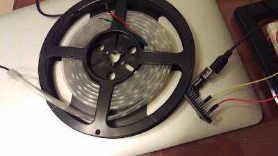
Here is the W2812B 5050 LED Strip I bought from an auction site. W2812B(3pins) is a newer generation and W2812(4 pins) is older generation. You may select the LED voltage (5V or 12V) of your preference as long as you have a suitable power source. 


Three Wire Easy Connections:
  • Arduino pin 6 to W2812B data pin
  • Arduino +5V to power source 5V
  • Arduino GND to power source GND
  • W2812B +5V to +5V power 5V/3A adapter (Power needed depends on how many LED you hook up)
  • W2812B GND to power 5V/3A adapter GND
  • Arduino GND to W2812B GND

Writing the code is not an easy task! So, you need LED Library to quick light up WS1812B LED Strip.  Get FastLED library from below link and install FastLED Library for your Arduino IDE.
FastLED Library: https://github.com/FastLED/FastLED

For more advanced control, you definitely want to visit FastLED Wiki to get more information. 

Load up the sample code from FastLED library "ColorTemperature".

You have to change the code to fit your Arduino environment settings:
1. LED_PIN = I use pin 6
2. NUM_LEDS = I have 120 in my LED Strip

Here is the source code:


#include <FastLED.h>


#include 

#define LED_PIN     6

// Information about the LED strip itself
#define NUM_LEDS    120
#define CHIPSET     WS2811
#define COLOR_ORDER GRB
CRGB leds[NUM_LEDS];

#define BRIGHTNESS  128


// FastLED v2.1 provides two color-management controls:
//   (1) color correction settings for each LED strip, and
//   (2) master control of the overall output 'color temperature' 
//
// THIS EXAMPLE demonstrates the second, "color temperature" control.
// It shows a simple rainbow animation first with one temperature profile,
// and a few seconds later, with a different temperature profile.
//
// The first pixel of the strip will show the color temperature.
//
// HELPFUL HINTS for "seeing" the effect in this demo:
// * Don't look directly at the LED pixels.  Shine the LEDs aganst
//   a white wall, table, or piece of paper, and look at the reflected light.
//
// * If you watch it for a bit, and then walk away, and then come back 
//   to it, you'll probably be able to "see" whether it's currently using
//   the 'redder' or the 'bluer' temperature profile, even not counting
//   the lowest 'indicator' pixel.
//
//
// FastLED provides these pre-conigured incandescent color profiles:
//     Candle, Tungsten40W, Tungsten100W, Halogen, CarbonArc,
//     HighNoonSun, DirectSunlight, OvercastSky, ClearBlueSky,
// FastLED provides these pre-configured gaseous-light color profiles:
//     WarmFluorescent, StandardFluorescent, CoolWhiteFluorescent,
//     FullSpectrumFluorescent, GrowLightFluorescent, BlackLightFluorescent,
//     MercuryVapor, SodiumVapor, MetalHalide, HighPressureSodium,
// FastLED also provides an "Uncorrected temperature" profile
//    UncorrectedTemperature;

#define TEMPERATURE_1 Tungsten100W
#define TEMPERATURE_2 OvercastSky

// How many seconds to show each temperature before switching
#define DISPLAYTIME 20
// How many seconds to show black between switches
#define BLACKTIME   3

void loop()
{
  // draw a generic, no-name rainbow
  static uint8_t starthue = 0;
  fill_rainbow( leds + 5, NUM_LEDS - 5, --starthue, 20);

  // Choose which 'color temperature' profile to enable.
  uint8_t secs = (millis() / 1000) % (DISPLAYTIME * 2);
  if( secs < DISPLAYTIME) {
    FastLED.setTemperature( TEMPERATURE_1 ); // first temperature
    leds[0] = TEMPERATURE_1; // show indicator pixel
  } else {
    FastLED.setTemperature( TEMPERATURE_2 ); // second temperature
    leds[0] = TEMPERATURE_2; // show indicator pixel
  }

  // Black out the LEDs for a few secnds between color changes
  // to let the eyes and brains adjust
  if( (secs % DISPLAYTIME) < BLACKTIME) {
    memset8( leds, 0, NUM_LEDS * sizeof(CRGB));
  }
  
  FastLED.show();
  FastLED.delay(8);
}

void setup() {
  delay( 3000 ); // power-up safety delay
  // It's important to set the color correction for your LED strip here,
  // so that colors can be more accurately rendered through the 'temperature' profiles
  FastLED.addLeds<CHIPSET, LED_PIN, COLOR_ORDER>(leds, NUM_LEDS).setCorrection( TypicalSMD5050 );
  FastLED.setBrightness( BRIGHTNESS );
}


Now compile and upload to Arduino Pro Mini through Arduino IDE and you will sett LED strips light up after few seconds.  It's really nice, isn't it!!


Here is the W2812B in motion.


Although it is so easy to light it up, my final goal is to make a Lightsaber with this LED strip. With the MP3 module I tested before, I wish I can put these two together without any issue.

Let's see if would able to do that!

Done.

============================================================

測試 WS2812B LED 燈條

常在網路上看到許多人秀出彩色的LED燈條,不但能顯示出各種顏色還能做出千變萬化的效果! 經過一番網路搜尋,原來這燈條叫做 WS1812B 5050(我還是不知道5050的由來,知道的再告訴我)。於是我上網拍去買了2公尺燈條,現在動手來試試吧!

做這個實驗所需的材料如下:
  • W2812B LED 燈條 60 LED/公尺 , 5V/3A (我買了2公尺)
    燈條有分防水和不防水的,你可以依自己的喜好做選擇。
  • Arduino Mini Pro * 1
  • 跳線數條 
  • 5V or 12V 電源/電池
WS2812B 5050 LED 燈條看起來如下。賣家賣的五公尺一捲,不過你可以買你要的長度。購買時要注意 W2812B只有3根腳位,如果是買到舊款的 W2812它有4根腳位,稍微注意一下。 燈條有兩種電壓 5V or 12V,我是選用 5V 的,不過你可以看看你手上的電源供應器或是電池來決定吧!


接法如下圖,只要一根資料線到 Pin 6 就好,記得要獨立提供給LED電源,因為它吃電還蠻兇的!
  • Arduino pin 6 to W2812B data pin
  • Arduino +5V to power source 5V
  • Arduino GND to power source GND
  • W2812B +5V to +5V power 5V/3A adapter (Power needed depends on how many LED you hook up)
  • W2812B GND to power 5V/3A adapter GND
  • Arduino GND to W2812B GND

首先,你要由此取得 FastLED Library: https://github.com/FastLED/FastLED 
如果你想要寫程式來控制燈條的話,請到 FastLED Wiki 去參考這個 Library 的用法。

接著,把 "ColorTemperature" 這支程式由 FastLED library 裡打開來。程式碼請參考上方英文的部份。只要修改兩行:

1. LED_PIN = Arduino 的資料 Pin, 我選用 6
2. NUM_LEDS = LED 串聯的總顆數,我的是 120 顆

接下來只要編譯再傳到 Arduino Pro Mini,2 秒後就可以看到燈條亮起來了!真漂亮!


看看做完,LED燈光閃爍的樣子吧!


這個WS2812B使用上真的是太容易了! 不過我的最終目標是把這燈條拿來做一把光劍。 只要把這個燈條加上我之前做過實驗的 DFplayer Mini MP3 模組, 這個算盤打的很如意!哈哈,看看我是不是做到吧!

完。
2015/04/26

A better Arduino IDE - Notepad++


VS Code is the best Arduino IDE Today!(2021-07)


Arduino IDE 1.6x has improved a lot over past few versions, such as adding line number, bug fixes, and many other features. However, Arudino IDE still has many miles to go to become a friendly editor for programmers. Syntax highlighting and programming language reference are programmer favorite features. However, they are not that fancy yet on the latest version of Arduino IDE V1.6.3.

I've been using Notepad++ (N++) for a while and Notepad++ is one of the most famous programming tools available for free!! Recently, I found josephdouce’s contribution on SourceForge that Joseph developed a N++ plugin for Arduino. Although it’s still in prealpha stage, it looks promising!

I would like to show you how to add N++ Arduino plugin into Notepad++ and use it as your editor.

Download Files:

  1. Download latest Notepad++ By Don Ho
    • You many select Installer, zip package, or 7z package
  2. Download latest Arduino IDE by Arduino.cc
    • Select Installer or zip package if you don't have admin access right
  3. Download N++ Arduino Plugin by josephdouce

Installation:

  1. Install Arduino by unzip the “Arduino-1.6.3-windows.zip” into your preferred folder or directly install it if you downloaded the Installer
  2. Install Notepad++ by unzip the download "npp.6.7.7.bin.zip" file into your preferred folder or directly install it if you downloaded the Installer
  3. Unzip N++ Arduino plugin zip files into an empty directory
Detailed N++ Arduino Plugin Settings:
  • First, let's import Arduino_Language_0.2.0.xml
    Start Notepadd++ application and click "Language", "Define your language..."
  • You should see "User Defined Language" window popup. Click on "Import..." and select the Arduino_Language_0.2.0.xml file  (This should be in the unzipped N++ Arduino plugin directory).  You will see import successfully message, then you may close this window.


  • Copy API files to Notepad++ plugins\APIs directory (This is where you installed the Notepad++).
    In my computer, it is in c:\Program Files\Notepad++\APIs\


  • In Notepad++, Click Preference


  • Click "Auto Completion" on the left (blue background) and then tick both "Enable auto-completion on each input" and "Function parameters hint on input", then close this window. (circled below)


How to use Arduino N++ Plugin:

When you start Notepad++ application, remember to click "Lanauages" then click on "Arduino". That's it! As you can see, as soon as you type, Notepad++ looks for variables or keywords from the XML file and show relevant candidates in a popup menu. As a programmer, it is a lot easier to just pick one up from the list. Isn't it?! ;)

Example:
A) I defined a variable called CheckStatus
B) As soon as I typed Check...
C) A list of suggested variable/command starting with letter C is listed in the box for you to pick up!

See below, Arduino language reference showing up automatically as you type!
This is really helpful!


Big thanks to these software contributors!!

How to invoke Arduino IDE for compiling and uploading to Arduino boards:
Quite few people was asking me if it's possible to compile code inside Notepad++. After few tries, I think it's impossible for now.  However, you may activate Arduino IDE inside Notepad++ with keystrokes you defined.

In Notepad++, Click "Run.."


You will see a popup window showed up. See illustration (A) below.
Click the 3 little dot button after the drop-down box and then select your Arduino executable file arduino.exe and then type "$(FULL_CURRENT_PATH)" right after the arduino.exe file. Double quotations are needed to make this work.

Here is mine for your reference:
"F:\arduino\arduino.exe" "$(FULL_CURRENT_PATH)"


Then Click "Save..." to assign a shortcut key. You will see another popup window(B). Tick the combination of CTRL, SHIFT, or ALT keys you like and pickup another key from the drop-down box. In my setup, I named it "Arduino" and selected CTRL + SHIFT + F5. From now on, I just need to hit the combination keys to invoke Arduino and bring the latest codes into Arduino IDE for compiling.

Hit CTRL + SHIFT + F5 you will see Arduino IDE invoking screen....


See below, codes in Notepad++ are identical as those in Arduino IDE.


PS: One problem though.... Each time you hit the combination keys, one instance of Arduino IDE will start and reside in the PC..... I don't have solution for this yet!

Thanks author Sriram Iyer for this tip: Using-notepad-plus-plus-instead-of-the-arduino-ide

End
================================================================

一套比 Arduino IDE 更好用的編輯器 - Notepad++ / Arduino N++ Plugin


Arduino 編輯器 V1.6x 雖然改進了不少,但是對寫程式的來說還是沒那麼好用。

Notepad++ 是一套很有名的文字編輯軟體。我自己曾使用 Notepad++ 寫 PHP,覺得它真的很好用。最近看到 SourceForge 上, 有位高手(josephdouce)寫了一套 N++ plugin for Arduino,雖然它只是 Prealpha 版本,但它已可以讓使用者在 Notepad++ 裡寫 Arduino,不但提供 Syntax highlight,變數及指令的提示, 也會給顯示語法使用方法及參數的提示,看來蠻有潛力的!

需下載的檔案:

  1. 由此下載最新版的 Notepad++ By Don Ho
    • 你可選擇要安裝版(Installer)或是壓縮檔(.zip or 7zip)再自行解壓縮也行
  2. 由此下載最新版的 Arduino IDE by Arduino.cc
    • 你可選擇要安裝版(Installer)或是壓縮檔(.zip or 7zip)再自行解壓縮也行
  3. 由此下載  N++ Arduino Plugin by josephdouce

安裝方法:

  1. Arduino: 選擇壓縮檔者,只要把 “Arduino-1.6.3-windows.zip” 解壓縮到你想要執行的目錄即可。 選擇安裝檔者,就按步驟執行即可。
  2. Notepad++: 選擇壓縮檔者,只要把 “npp.6.7.7.bin.zip” 解壓縮到你想要執行的目錄即可。 選擇安裝檔者,就按步驟執行即可。
  3. N++ Arduino plugin: 解壓縮 "Notepad++.Arduino.0.2.0.zip" 到自己想放的目錄即可。
N++ Arduino Plugin 安裝與設定:
  • 匯入 Arduino_Language_0.2.0.xml 設定檔
    開啟 Notepadd++ 然後點選 "Language/程式語言", "Define your language.../定義程式語言" 如下圖:
  • "User Defined Language/自訂程式語言" 視窗會跳出來。點選 "Import.../匯入"(見下圖) 然後由視窗裡點選 Arduino_Language_0.2.0.xml 檔案。 (這個檔案就是你剛剛解壓縮N++ Arduino plugin的目錄)。  如果匯入完成,你會看到完成的提示視窗。


  • 從N++ Arduino plugin解壓的目錄裡,把 API  "Arduinolbs" 目錄夾 整個 copy 到 Notepad++ plugins\API 目錄底下 ( Notepad++ 執行檔安裝位置裡有一個 \plugins\APIs 的目錄)  在我自己的電腦,Notepad++ 是安裝在 c:\Program Files\Notepad++\APIs\ 底下


  • 在回到 Notepad++, 點選 "Preference/自訂"


  • 從左邊點選 "Auto Completion/自動完成功能"  然後把 "Enable auto-completion on each input/啟動自動完成功能" 和 "Function parameters hint on input/自動顯示功能參數提示", 打勾 ,關掉視窗即設定完成。 參考下圖:

Arduino N++ plugin for Notepad++ 使用方法:

只要安裝成功,使用方法非常簡單! 打開 Notepad++, 在程式語言的清單裡選擇 Arduino 即可!
往後只要你一邊打字, N++ plugin 會把相關的指令或是你使用過的變數在一 個小視窗上列出來。這樣一來,你可以挑想用的變數或是指令, 降低變數/指令使用出錯率。

例如:
A) 我定義了 CheckStatus 變數
B) 只要我在 Notepad++ 裡打了 Check
C) 所有指令或是變數是由 C 開頭的都會顯示在小視窗裡,CheckStatus 就在最底下,如下圖:

Arduino 指令使用方法及參數也會自動顯示出來了! 對新手來說, 這樣可以減少查閱指令的使用方法,是不是太方便了!


如何在 Notepad++ 裡呼叫 Arduino IDE 來編譯及上傳到Arduino上:

有不少人問我,能不能在Notepad++ 裡直接呼叫 Arduino IDE 來編譯及上傳。找了網上的一些資料,發現目前還沒有方法可以做的到。不過,你可以自行定義快速鍵來呼叫 Arduino IDE 並且把正在編輯的程式碼直接傳到 Arduino IDE 裡。

在 Notepad++ 裡, 點選 "Run.."


你會看到一個 Run... 的視窗跳出來如下圖(A)
點一下有3個小點的鈕,然後選取你的 Arduino 的執行檔,再加上左右側的雙引號在路徑的前後,空一格,再加上 "$(FULL_CURRENT_PATH)" 

在我的PC上,它看起來應該像這樣:( 引號有四個,都要打上去才行)
"F:\arduino\arduino.exe" "$(FULL_CURRENT_PATH)"


按下 "Save.../存檔" 然後你會看到視窗(B) 自行定義快速鍵,把你想要指定的快速鍵打勾,再從下拉選單裡,選一個自己喜歡的組合,然後在 Name: 那裡自己取一個檔名來儲存。我自己取為 Arduino 並選取了 CTRL + SHIFT + F5. 按 OK, 關掉視窗。

往後我只要按下  CTRL + SHIFT + F5 在 Notepad++ 裡,即可直接呼叫 Arduino IDE 來編譯及上傳。


按下CTRL + SHIFT + F5 鈕後,會看到這個畫面表示 Arduino IDE 開始啟動:


右側視窗的 Notepad++ 呼叫 Arduino IDE, 你可以看到左側是 Arduino IDE 裡的程式碼和右側
Notepad++ 裡的程式已經同步。


PS: 有一點小小的問題.... 每次你呼叫一次 Arduino IDE,它的程式就會長註一個在電腦裡。我還不知道有沒有解法!

謝謝網友 Sriram Iyer 網誌裡提供在 Notepad++ 裡呼叫 Arduion IDE 的方法: Using-notepad-plus-plus-instead-of-the-arduino-ide


結束


2015/03/15

Weekend Project – Arduino Temperature Meter

Found an interesting temperature probe on the auction site and I decided to acquire two pieces to test them out. With the LCD module, it seems making a temperature meter is not that hard at all.

In this tutorial, I will show you how to make a temperature meter that allows you to measure temperature with a probe and display current, highest, and lowest temperatures on LCD module.

After I made this, I left it on the desk almost a week and it’s still working! 
I guess it’s time to share how I did this.
See photo below:


Material Needed: 
  • Arudino Mini Pro * 1
  • LCD Module 4 x 20 (J204A) * 1
  • Temperature Probe (DS18B20) * 1 
  • Protoboard * 1 
  • 22k resistor * 1
  • Few jumper wires
Wiring:
  1. Arduino-GND to GND 
  2. Arduino-VCC to VCC 
  3. Temperature probe-GND to GND 
  4. Temperature probe-VCC to VCC 
  5. Temperature probe-Data to 2.2K resistor to VCC 
  6. LCD-GND to GND 
  7. LCD-VCC to VCC 
  8. LCD-SDA to Arduino A4/SDA 
  9. LCD-SLC to Arduino A5/SLC 
  10. Protoboard VCC/GND to 5V DC power source 
  11. Slide switch to VCC/GND (For LCD on/Off, but not shown below)
Connection:

LCD Module:

//Library version:1.1
#include <Wire.h>
#include <LiquidCrystal_I2C.h>
//Used for DS18S20 Temperature sensor
#include <OneWire.h>
#include <DallasTemperature.h>

/*Define for DS18S20 data pins
*  This data pins needs to connect 220 Om resister and to 5V to work
*/
#define ONE_WIRE_BUS 4 

//Define for LCD display pins, SLC 3, SDA 2
#define SCL_CLOCK_PIN 3
#define SDA_DATA_PIN 2

//Initialize OneWire library for temperature sensor
OneWire oneWire(ONE_WIRE_BUS);
DallasTemperature sensors(&oneWire);

// set the LCD address to 0x27 for a 20 chars and 4 line display
LiquidCrystal_I2C lcd(0x27,20,4);  

float HighestTemp = 0.0;
float CurrentTemp = 0.0;
float LowestTemp = 0.0;

void setup()
{
  // start temperature sensor
  sensors.begin();
  sensors.requestTemperatures(); //get temperature
  // initialize the LCD
  //You may setup your own clock pin(SCL), data pin(SDA) 2013-12-14
  //Wire.beginOnPins(SCL_CLOCK_PIN, SDA_DATA_PIN);
  lcd.init();
  
  lcd.backlight();
  
  //Set lowest, highest temperatues 
  CurrentTemp  = sensors.getTempCByIndex(0);
  HighestTemp = CurrentTemp;
  LowestTemp = CurrentTemp;
  
  lcd.setCursor(0,0);  
  lcd.print(F("=Temperature Meter="));

  lcd.setCursor(0,1);
  lcd.print(F("Highest: "));
  LCDshowNum(8,1,HighestTemp);    
     
  lcd.setCursor(0,2);
  lcd.print(F("Current: "));
  LCDshowNum(8,2,CurrentTemp);  
    
  lcd.setCursor(0,3);
  lcd.print(F("Lowest: "));
  LCDshowNum(8,3,LowestTemp);     
}


void loop()
{ 
  sensors.requestTemperatures(); //get temperature

  //Get Current
  CurrentTemp = sensors.getTempCByIndex(0);
  LCDshowNum(8,2,CurrentTemp);   
  
  //Check if Hightest
  if(CurrentTemp > HighestTemp){
     HighestTemp = CurrentTemp;
     LCDshowNum(8,1,HighestTemp);     
  }

  //Chekc if Lowest
  if(CurrentTemp < LowestTemp){
    LowestTemp = CurrentTemp;
    LCDshowNum(8,3,LowestTemp);
  }

  delay(1);
}

/*
* LCDshowNum
* LCD display location: x, y
* Float n: temperature to display
*/
void LCDshowNum(int x, int y, float n){
  lcd.setCursor(x,y);
  lcd.print(n);
}
In the video, I had three bottles filled with hot water from drinking fountain, room temperature tap water, and ice cube water. I told my son to place the probe into each bottle and we observed the changing in temperatures.   It was a lot of fun to see the temperature goes high and low!


My son asked me “Is there a way to see temperature drop to 0 or minus”? We quickly found the answer from Internet. The answer is so simple, just put salt on top of ice cubes without water. With in a minute, the temperature dropped to -11 Celsius degrees (12 degrees in Fahrenheit). Actually, the lowest temperature we got was Celsius -14.31 (6.242 degrees in Fahrenheit), but not recorded in the video. See video below.


I hope you enjoy this tutorial and have fun with your kids!

Stonez

自製 Arduino 溫度測量機

在這個教學中,我會教你們怎麼做一個可以讓你在LCD模型上測量出目前的溫度,最高的溫度和最低的溫度的「溫度測量機」。在我完成它之後,我把它放在桌子上大約一個星期後,它還在運作呢!☺ 我覺得是時候該跟大家分享我是怎麼製作它了。

 看看我的溫度測量機:


需要材料: 

  • Arudino Mini Pro * 1 
  • LCD 模組 4 x 20 (J204A) * 1 
  • 溫度探棒 (DS18B20) * 1 
  • 洞洞板 * 1 
  • 22k 電阻 * 1 
  • 幾根跳線
 線路連接方法:
  1. Arduino-GND to GND 
  2. Arduino-VCC to VCC 
  3. Temperature probe-GND to GND 
  4. Temperature probe-VCC to VCC 
  5. Temperature probe-Data to 2.2K resistor to VCC 
  6. LCD-GND to GND 
  7. LCD-VCC to VCC 
  8. LCD-SDA to Arduino A4/SDA 
  9. LCD-SLC to Arduino A5/SLC 
  10. Protoboard VCC/GND to 5V DC power source 
  11. Slide switch to VCC/GND (For LCD on/Off, but not shown below)
電路圖如下:


底下的影片中,一共有三個瓶子,分別裝著熱水,冰水和常溫的水。 我請我的兒子把溫度探棒分別置入到每一個瓶子裡,再觀查各別溫度的變化。


我兒子問我:「有沒有可能讓溫度降到零度或更低?」我們很快的從網路上找到了答案。其實很簡單,只要在冰塊上撒鹽。過了大約一分鐘,溫度就降到了-11度 C(我們最低該溫度降到到-14.31度 C)!看著溫度快速的上升又急快的下降真有趣!請看底下的影片:


 找個時間做這個Arduino 專案,再和小朋友一起同樂吧!

 Stonez

2015/03/01

Arduino - DFPlayer Mini MP3 Module


Arduino - Test DFPlayer Mini MP3 Module


I found DFPlayer mini MP3 module on China auction site Taobao when I was looking for a MP3 player module for an Arduino projects.  This module is quite small and it only require few pins connections to Arduino and a speaker to work.  Looks really nice for my little project.

Actually, the module is quite capable and complicated, if you were interested, please visit this page.

This tutorial here is just to show you how to connect DFPlayer module with Arduino and speaker and the Arduino sketch provided here just to play few sample sounds I collected from Internet.

First, I recycled a 2W, 4Omh small speaker from this little music box.


Material Needed:
  1. DFPlayer Mini module 
  2. Speaker - DFPlayer module support to to 3W
  3. SD card - 2GB ~ 32GB formatted with FAT or FAT32
  4. MP3 / WAV - audio files
  5. Arduino mini Pro
  6. Few jump wires
As you can see the illustration below I made in Power Point, hardware connection is quite simple
(Forget about the cross lines...these lines are NOT supposed to be crossed.. :)
* Note: You have to separate DFPlayer Mini Module power from Arduino power or you will hear very loud noises (It took me two days to figure out this!)

***********
UPDATE:  Someone left a message in this blog below, please try it out!

Hello everybody! There is another solution for getting rid of noise. Just put down DC voltage to 4.0 - 4.3 Volts. Arduino is still able to operate and DFplayer recommends to use 4.2V, my experiments prove this.

***********

Here is a photo of my Arduino with DFPlayer Mini connection:


*Important note for audio files. Careful read notes below will save you a lot of precious time!
  • DFPlayer Mini read both MP3 and WAV files.
  • All audio files must be placed under /mp3 folder.
  • Audio file must be named 0001.mp3, 0002.mp3.....0255.mp3 (4 letters not 2 or 3 letters)
  • Audio file names can have any characters after 4 digits, such as 0001_Bruno_Mars_Count_On Me.mp3 
  • Tested few under 1 second WAV files and they did not work
  • If one of the audio file is removed from SD cared, DFPlayer still can find it and play it! Weird! In the end, I formatted the SD card to make DFPlayer to play the music I specified.
  • Delay(seconds); You have to specify number of seconds delay for the audio file to play completely or the next audio file might be started before current audio is over!
  • mp3_play (74); means play audio file 0074.mp3
The code below is from the vendor's website and it worked without much modification.

Programming Code here:


/*
 * Copyright: DFRobot
 * name:  DFPlayer_Mini_Mp3 sample code
 * Author:  lisper 
 * Date:  2014-05-30
 * Description: sample code for DFPlayer Mini, this code is test on Uno
 *   note: mp3 file must put into mp3 folder in your tf card
 */

#include <softwareserial.h>
#include <dfplayer_mini_mp3.h>

void setup () {
 Serial.begin (9600);
 mp3_set_serial (Serial); //set Serial for DFPlayer-mini mp3 module 
 mp3_set_volume (10);
}

void loop () {        

 mp3_play (1); //play 0001.mp3
 delay (10000); //10 sec, time delay to allow 0001.mp3 to finish playing

 mp3_play (2);
 delay (5000);

 mp3_play (5);
 delay (5000);

 mp3_play (20); //play 0020.mp3
 delay (9000);

 mp3_play (81);
 delay (6000);

 mp3_play (74); //play 0074 mp3
 delay (6000);

}
Here is the video:
Done.

Arduino - 測試 DFPlayer Mini MP3 播放模組

最近在大陸拍賣網上找到一個 Arduino MP3 播放模組(DFPlayer Mini),它支援最大32GB SD卡,又可以由 Arduino 下個  Play 的指令就能由SD 卡上播放 MP3 & WAV檔案。加上體積很小一片又只要連接幾支腳位到 Arduino 就能運作了,二話不說就淘了兩片來試試它的功能。

DFPlayer Mini 它的功能真的很多, 有興趣的朋友可以到這裡閱讀 DFPlayer Mini 的介紹!

這個測試主要是測試 DFPlayer Mini MP3 播放模組的功能,所以只需要下列的東西即可:

  1. Arduino mini Pro
  2. DFPlayer Mini 模組 
  3. Speaker - 最高支援到 3W
  4. SD card - 2GB ~ 32GB 以 FAT or FAT32 格式化
  5. 洞洞板 / 跳線
  6. MP3 / WAV 格式的音效 or 音樂檔案

手上剛好有一個壞掉的音樂播放器,我把喇叭拆下來看了一下,剛好是 2W的,可以拿來用。


下方是我自己在 Power Point 上畫的線路示意圖:
(Forget about the cross lines...these lines are NOT suppose to be crossed.. :)
* 注意: 不要直接把 Arduino 的 5V 給 DFPlayer Mini 使用,一定要分別供給 DFPlayer Mini 電源,不然喇叭會發出很大的雜音,我花了兩天才發現這個問題。

以下照片是我實際連接的樣子:

* 以下是使用 DFPlayer Mini Module 的注意事項,請仔細閱讀,可以幫你節省很多時間!

  • DFPlayer Mini 可以讀取 MP3 & WAV 檔案格式,但試過檔案長度1秒以下無法播放。
  • 所有音樂檔案一定要放在 /mp3 資料夾裡
  • 音樂檔案名稱一定要使用 4 個字,如 0001.mp3, 0002.mp3.....0255.mp3 
  • 音樂檔案超過4個字後則無限制,像是 0001_Bruno_Mars_Count_On Me.mp3 是沒問題的。
  • 如果你從 SD 卡上刪掉某個檔案,DFPlayer Mini 還是有辦法把它播出來,好怪!後來我從新格式化 SD 卡才成功播放我要的音樂檔案。
  • Delay(sec); 這個指是是告訴 Arduino 你要播放音樂的長度,如果你給的秒數不足,而下個指令又是要播另一首,則 Arduino 就會把目前播放中斷,而繼續播下一首。
  • mp3_play (74); 這個指令是播放 0074.mp3 這個音樂檔。

Arduino 程式碼請參考上面。

請看下方實際運作影片:
完成。

2015/02/15

Android control color RGB LED using HC-05 Bluetooth module with Arduino (Part II)

 Android control color RGB LED using HC-05 Bluetooth with Arduino(Part II)

You probably have seen my first part of Arduino hardware setup tutorial. If you haven't please visit here: My previous Arduino (Part I tutorial).

After few weeks of struggling with MIT App Inventor 2, I finally completed my second generation of Color LED Controller V2.0 App.


Basically, 2nd generation of Android APP shows a color RGB wheel on the display and you might pick any color on the display to wirelessly change the RGB color accordingly. With glide/drag capability built in the App, you may glide your finger through the color wheel to see RGB LED changes color gradually.

For the Arduino part, all the code stays the same. Yes, I haven't modified a single line of code in the Arduino.

Please watch the video below to see how it works! :)


Here are the App coding screenshot for your reference:

************************************************************
0) Sorry blog readers....here are the two missing global variable blocks.... :-)
*************************************************************

1) App Inventor 2 screen initialisation code.


2) Android to HC-05 Bluetooth connection code.

3) The button to turn on/off LED


4) Code for touch on the color wheel to change LED color


 5) Code for Glide/Drag finger across the color wheel to see the color change accordingly

6) Here is the code for RGB color code split and then send to Arduino to change RGB LED color through Bluetooth.


How RGB Color Code was Processed:==*==*==*====*====*====*====*====*====*====*====*====*====*====*==
In App Inventor, the color code string after [Split Color] will be something like "(255 255 255 255)". What I need in Arduino is only R, G B, so I have to remove last 255.

*** The last 255 is a string in color code and it will be 255 all the time***

For easier string processing, I replace " "(space) with a "." (dot).
Then, I send each color code string to Arduino as "255.255.255)"

In side Arduino, I could split R, G, and B easily with the "."(dot) and use ending ")"(parenthesis) to check if the color code is complete or not.
==*==*==*====*====*====*====*====*====*====*====*====*====*====*==


After you put all these codes into MIT App Inventor 2, you should able to build the code on your PC/Mac to generate an Android .APK to place on your Android phone to test it out with Arduino.

Please do not ask me to post the original code here for you to download. If I do so, no one would download my App from Android Play Store! ;)

If you don't want to create this App yourself, please Download this App here!

Happy coding!!

Stonez


--------------------------------------------------------------------------------------------------------------------

Part II - Android HC-05 藍芽連線控制彩色 RGB LED


你們可能已經讀過我上一次的Arduino硬體設定和下載了第一代APP。如果還沒看過,可參閱我上一個教學 Android 藍芽連線控制彩色 LED

經過幾個禮拜的努力,我終於完成我第二代的 LED 遙控 APP 了。

基本上第二代的設計是一個可以任君挑選顏色RGB調色盤。你可以點選你想要的顏色或是用手指滑過螢幕上的任一個顏色,應用程式會透過藍芽把顏色代碼送變 Arduino 來改變 RGB LED 燈泡的顏色。

Arduino 程式碼的部分是維持跟之前一樣,一行程式碼都不用更改就能使用了。

請先看一下底下影片的示範:


MIT App Inventor 的程式代碼如下:


1) App Inventor 2 Screen1 初始化設定:


2) Android 連結到 Arduino + HC-05 藍芽模組程式碼:

3) 這組程式碼是用來開關 RGB LED


4) 這組程式碼是用來回應點選的顏色並改變 LED 顏色


 5) 這組程式碼是用來控制滑過螢幕並即時改變其顏色

6) 這組程式碼是用來把顏色編碼成 RGB 代號並且把這組編碼顏色代號以藍芽送到Arduino該LED依照代碼變色。


只要按照以上程式碼輸入MIT App Inventor 2後,你就應該可以做成一個APK檔案。
Sorry, 我不會把原始檔整會貼在這裡,所以請你動手做做看吧!!

如果不想動手做,那請從 Play Store 下載吧

Stonez