上次把電子零件通通焊到板子上了,今天來完成這個專案吧!
首先,要先找到提供電源給Arduino 的方法。看了網路上很多人都說自製變壓器要小心安全的問題,大都建議用現成的變壓器,所以我拿了手上一個手機變壓器來當做電路板的電源。
After I soldered all components on the perfboard, let's complete this project today! First, I need to find a way to provide power to our perfboard. Many people on the internet recommended to use a mobile phone charger instead of making one themselves due to safety concerns. So I got a spare HTC charger for my project as shown below.
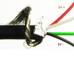
把USB電線剪斷小端(MicroUSB) 到適合的長度,把外皮剝開,裡面會有四條不同顏色的電線如下圖,紅是正極,黑是負極。把正負極焊到電路板上。
Carefully cut the microUSB end and pelled the shielding off the cable. In there, you will be four wires with GREEN, WHITE, RED, BLACK. Solder the RED and BLACK to positive and negative on your perfboard.
再把正負極焊在電路板上後,記得插電到電路板上先試試功能是否正常。
After soldered the wires, plug charger and test your board to see if it's working.
這是我房間裡的燈,它由開關來開啟,每次開關一次,它會循環:3個燈/關,5個燈/關,2個燈/關,小夜燈/關。
My bedroom light looks like this below. It has a switch located at the entrance of the bedroom. The switch works like this. For every switch on/off, it cycles through 3 lights/off, 5 lights/off, 2 lights/off, night lights/off.
把螺絲鬆開後,即可拿下玻璃片。
Carefully loosen the screen on the bottom and remove the decorative glass away.
把中間螺絲柱轉下來,記得順便把所有的燈泡轉下來,取下固定燈枱的兩個螺絲後,裡面還有兩條110V電線,我們即可拆下燈架。
Remove the center long screw as well as all light bulbs. Then remove two fixing screws on the light base set, but there are two more wires inside we need to take care!
再把下圖110V的電黑/紅電線上的膠布用刀片劃個幾刀即可取下膠布。緊接著,小心的取下框架。
小秘訣:注意看下方的照片裡,我有用一條小的電線把燈框架綁在上方的鐵柱上,這樣作業時才不會需要一直拿著燈架,手真的會很酸喔!
Carefully remove the isolation tape and detach the 110v wires with a utility knife.
Tip: If you look at the photo below, I tight a red wire to the steel beam and the light frame. Therefore, you don't need hold the light frame and try to detach isolation tape at the same time. This save me a lot of effort.
把燈的框架取下後放在地上。找個適當位置放置電路板。
記得,電路板放的位置不能擋到燈泡及螺絲要固定的位置。
Position the perfboard in an idea location without blocking the light bulbs from installing and removing later as well as avoid the screw's holes and wires.
燈座因為空間有限,我用電鑽在燈枱座上鑽個洞,把變壓器放在橙枱座內框裡,電路板則是放在外邊。
Since there is limited space on the light frame, I placed the phone charger inside the light base and the perfboard outside the light base. Drill a hole on the light base to allow the USB charging cable to go through.
找一片絕緣的材質(我是用一片塑膠片把它在電路板底下)再用束線帶把它固定好。
接著,我再用電鑽在燈座灰色的地方鑽個洞,找支螺絲把電路板鎖上固定好。
Place an isolation material between light base and perfboard (I found a piece of plastic from a cookie case) and tight them together with a cable tight.
Drill a hole on the light base and tight the perfboard and light base with a screw as shown below.
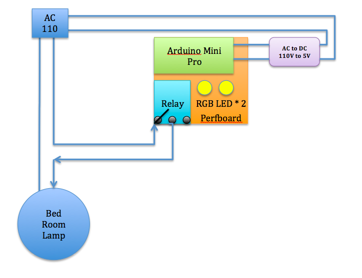
接線的方式如下圖,由天花板上的110V 正負極各接到手機的變壓器,它會提供5V電源給電路板。另外110V負極再接到燈座本身,正極接到電路板的繼電器模組 "常開",再由"共用"極接回到燈座上。
Phone charger retrieves power from 110v power line from the celling. Phone charge constantly provide power to the perfboard. See the illustration below for my complete wiring.
由110V接到手機變壓器上時,記得絕緣要做好,不然可能會短路造成災害可不好⋯⋯
我用的是絕緣膠布,多纔幾圈才安全!畢竟大家只是因為樂趣來 DIY,沒必要賠上身家財產。
When connect 110v power line to phone charger, please make sure the isolation is done properly. I used the isolation tape and tight them 3~4 times to ensure it's isolated. After all, there is no reason to risk your life or property for the sake of DIY.
如上面說明,我由天花板上的110V 正負極各接到手機的變壓器,它會提供5V電源給電路板如下圖:
As mentioned before, I placed the phone charger inside the light base.
如下圖:110V負極再接到燈座本身,正極接到電路板的繼電器模組 "常開"(左側),再由繼電器模組"共用"(中間)極接回到燈座上。一定要接繼電器模組 "常開",不然你原來的電燈開關就會失效了!
See below: Connect 110v positive to relay "NO or Normally Open" on the left, and COM "Common connection" in the middle should connect back to 110v negative.
把從繼電器模組"共用"(中間)極(原來的正極)接回到燈座。
See the wiring below, both positive and negative are now connecting back to the celling 110v wire.
好了,裝上一兩個燈泡試試原來牆上的開關是否和原來一樣能正常的工作。接著,再試試搖控器是否能正常的開關電燈,我很幸運,一切都能正常運作。注意看下方紅色圈起來的地方,它是我上次固意延伸出來的紅外線接收器,我原本把它放在電燈玻璃的裡面,但搖控無法控制,不知是不是距離太遠的關係,只好再把它拉出來外緣,讓搖控更順暢。
Ok, before you tighten the light frame and decorative glass back to the celling, try to put on few light bulbs and test out the remote to see if they are working as expected. See the red circle below, that's the IR receiver that I used an extended wire from my perfboard to the rim of the light to get better IR reception.
試試用電視搖控器來改變燈的顏色!
I tried use the TV remote to change the LED color on the perfboard.
再變不同的顏色!
Change the color agagin with my TV remote.
各位可以看看實際運作的影片如下:
Please check the fully functional system in video as below.
第一個Arduino實用專案終於完成!!
This is first practical Arduino project that I have done by myself!!


No comments:
Post a Comment