I just purchased my Creality Ender 3 Pro and after modified the HW(will write what I have modified later) and turning, turning, and more turning. It finally worked well after a month.
Many people in the Facebook group discussing what parts could self-print to upgrade. One of them was the dampening feet to reduce noise. I tested the noise level in dB with Google Science Journal APP. The test duration was 31 seconds with PLA, 0.2 layer high, 100% infill. Please see the results below.
My Testing Results
In my test, Dampening feet reduced about 11 dB* about 10 times lessnoise! This is quite amazing!
However, few people in Facebook groups mentioned that there might be other disadvantages, such as wobbling when printing tall objects and these feet might broken easily.
* A sound 10 times more powerful is 10 dB.
* A sound 100 times more powerful than near total silence is 20 dB.
Source: How stuff works
Print with Dampening Feet
Test Duration: 31 seconds Average: 22 dB Max: 37 dB
Google Science Journal App recorded the noise level
I have printed the same Dampening feet to get the more accurate noise level.
See the printing of a Damping feet in action (With Dampening feet)
Print without Dampening Feet
Test Duration: 31 seconds
Average: 30 dB
Max: 48 dB
Google Science Journal App recorded the noise level
The noise was recorded during printing the Dampening Feet.
Download .STL files
All the .STL file can be downloaded from Thingiverse.com
Based on my previous project (Joystick Control Gimbal), I slightly modified it into a Light Tracking device. It took me about two days to fine-tune the Light Tracking Gimbal to move smoothly and hold its position while light source is not moving.
Goal of this tutorial
Let's see the video below to see what's the final result of this tutorial.
Gimbal Panel Area
There are Top Left, Top Right, Bottom Left, and Bottom Right.
In each area, there is a light sensor.
Programming Logic:
Get reading from 4 photo sensors
I sample each sensor 10 times and then get the average value to ensure the readings are more stable
Get average of each side
Top side value = (Top left + Top right) / 2
Bottom side value = (Bottom left + Bottom right) / 2
Left side value = (Top left + Bottom left ) / 2
Right side value = (Top right + Bottom right ) / 2
Compare all four sides to see which side has bigger value
Move the servo towards the biggest side among four side
Tolerance variable is in control whether to move or not based on how much differences among four sides. If reading values from four sides were within the range of 100, then keep the Gimbal static(Hold it's position) (default value = 100)
Tolerance variable is the most important variable to ensure the Gimbal holds its position when four light sensors get values within the defined tolerance!
Component Needed for this project
Arduino Nano * 1
SG90 Servo * 2
Light sensors * 4
10K Resistors * 4
Prontoboard * 1
Many jump wires
Extra long wires for photo sensor connect * 4
Heat shrink tube 2cm * 4
Tools Needed
Soldering gun * 1
Diagonal cutting pliers * 1
Screw driver * 1
Few screws * 10
Double sided tape
Schematic: (I use fritzing for this schematic)
Program Code:
************************************************************* *** Please click subscribe my YouTube Channel before use the code *** There is no restriction, but I would be really appreciated *** if you did. Thank you! ************************************************************** ************************************************************* *** 在 Copy 底下程式碼之前,請按下底下按鈕,訂閱我的 YouTube 頻道! *** 雖沒有強制規定,不過如果你有訂閱的話,非常感謝你! **************************************************************
/**
   Author: Kevin Chen AKA Stonez56
   My Blog to see more tutorials: https://stonez56.blogspot.com
   Date: 2019/05/11 The day before mother's day

    Program function flow
   1. Reading four light sensor values
   2. Average top two(Top left, Top right), bottom two(Bottom left, Bottom right)
   3. Average left two(Top left, Bottom left), right two (Top right, Bottom right)
   4. Compare 4 averaged value and make servo mave toward the biggest number side

   v0 Light traking Gimbal base to get readings
   v1 Write servo code in and move servo accordingly

                    |
         Top left   |     Top right
   -----------------+----------------------
     Bottom left   |  Bottom right
                    |
*/
#include <Servo.h>
Servo servo1_x;
Servo servo2_y;

//Light Sensor Pin definitions
const uint8_t  light_top_left_PIN = A6;
const uint8_t  light_bottom_left_PIN = A5;
const uint8_t  light_top_rigth_PIN = A2;
const uint8_t  light_bottom_right_PIN = A1;
//Potentiometer pin
const  int potPIN = A0;
//Servo pins
const int servo1_x_pin = 2;
const int servo2_y_pin = 4;


//User define variables
// Gimbal movement tolerance 50~255
byte gimbal_movement_tolerance = 100;
//Photo sensor max reading times for average (for more accuracy)
byte max_reading = 10;
// define original servo angle
uint8_t originalAngle = 92;
uint8_t x_last = originalAngle;  // X last postion
uint8_t y_last = originalAngle; // Y last postion
uint8_t moveSpeed = 10;  //How fast show this Servo move
uint8_t maxSpeed = 50; //Max speed
uint8_t minSpeed = 1;
uint8_t y_minAngle = 1;  //Mimum angle
uint8_t y_maxAngle = 180;  //Maximum angle
uint8_t x_minAngle = 90;  //Mimum angle
uint8_t x_maxAngle = 180;  //Maximum angle

void setup() {
  Serial.begin(57600);

  pinMode(light_top_left_PIN, INPUT);
  pinMode(light_bottom_left_PIN, INPUT);
  pinMode(light_top_rigth_PIN, INPUT);
  pinMode(light_bottom_right_PIN, INPUT);

  servo1_x.attach(servo1_x_pin);
  servo1_x.write(originalAngle); //move servo to defined angle
  servo2_y.attach(servo2_y_pin);
  servo2_y.write(originalAngle); //move servo to defined angle

  pinMode(LED_BUILTIN, OUTPUT);
  digitalWrite(LED_BUILTIN, LOW);

}

void loop() {
  char moveTowards = ' ';


  int potValue = analogRead(potPIN);
  Serial.print(F("potValue: "));
  Serial.println(potValue);
  moveSpeed = map(potValue, 0, 500, minSpeed, maxSpeed);
  Serial.print(F("moveSpeed: "));
  Serial.println(moveSpeed);
  moveTowards = getFacingToward(); //find out which side to move


//  Serial.print(F("moveTowards: "));
//  Serial.println(moveTowards);
  moveServo(moveTowards);

  delay(80);
}

void moveServo(char moveTowards) {


  //previous position were stored in x_last, y_last
  switch (moveTowards) {
    case 'T': //Move towards top
      if (x_last - moveSpeed < x_minAngle) {
        x_last = x_minAngle;
        servo1_x.write(x_last);
      } else {
        x_last -= moveSpeed;
        servo1_x.write(x_last);
      }
      break;
    case 'B': //Move towards bottom
      if (x_last + moveSpeed > x_maxAngle) {
        x_last = x_maxAngle;
        servo1_x.write(x_last);
      } else {
        x_last += moveSpeed;
        servo1_x.write(x_last);
      }
      break;
    case 'L': //Move towards left
      if (y_last - moveSpeed < y_minAngle) {
        y_last = y_minAngle;
        servo2_y.write(y_last);
      } else {
        y_last -= moveSpeed;
        servo2_y.write(y_last);
      }
      break;
    case 'R':
      if (y_last + moveSpeed > y_maxAngle) {
        y_last = y_maxAngle;
        servo2_y.write(y_last);
      } else {
        y_last += moveSpeed;
        servo2_y.write(y_last);
      }
      break;
    default:
      //Don't move servo
      break;
  }

}

/**
   This fuction get reading max_reading times and return average
   if it sees an 0, it will skip it
*/
int averageReading(int PIN, byte max_reading) {
  int total = 0;
  int current = 0;

  for (byte i = 0; i <= max_reading; i++) {
    current = analogRead(PIN);
    if (current == 0) {
      current = analogRead(PIN);
    }
    total += current;
  }

  return total / (max_reading);
}

/**


   Parameters: N/A
   Return: char; T, B, R, L to indicate the moving directoin
                       '-' means not moving at all
*/
char getFacingToward() {
  //1. Read each pin max_reading times

  int top_left = averageReading(light_top_left_PIN, max_reading);
  int bottom_left = averageReading(light_bottom_left_PIN, max_reading);
  int top_right = averageReading(light_top_rigth_PIN, max_reading);
  int bottom_right = averageReading(light_bottom_right_PIN, max_reading * 3);

  //Show photo sensor readings...
  Serial.print(F("Top left-A6: "));
  Serial.println(top_left);
  Serial.print(F("Bottom left-A5: "));
  Serial.println(bottom_left);
  Serial.print(F("Top right-A2: "));
  Serial.println(top_right);
  Serial.print(F("Bottom rightA1: "));
  Serial.println(bottom_right);

  //2. Get max value sides(two averaged, see above)
  byte go_direction[4] = {0, 0, 0, 0};
  int toward[4] = {0, 0, 0, 0}; //Top, Bottom, Left, Right
  toward[0] = (top_left + top_right) / 2 ;
  toward[1] = (bottom_left + bottom_right) / 2 ;
  toward[2] = (top_left + bottom_left) / 2;
  toward[3] = (top_right + bottom_right) / 2;

  //3. Add all side and average,
  //    if each side is within the tolerance then don't move Gimbal
  //    average = toward[0] +...toward[3]
  //    average - toward[0] .... toward[3], if all within gimbal_movement_tolerance, then no move
  int total_toward = 0;
  total_toward += toward[0];
  total_toward += toward[1];
  total_toward += toward[2];
  total_toward += toward[3];
  //get average
  int total_average = total_toward / 4; //4 sides
  Serial.print(F("total_average:"));
  Serial.println(total_average);
  //    if each side is within the tolerance then don't move Gimbal
  boolean shouldMove = false;
  //else move the gimbal
  if (total_average - toward[0] > gimbal_movement_tolerance) shouldMove = true;
  if (total_average - toward[1] > gimbal_movement_tolerance) shouldMove = true;
  if (total_average - toward[2] > gimbal_movement_tolerance) shouldMove = true;
  if (total_average - toward[3] > gimbal_movement_tolerance) shouldMove = true;

  Serial.print(F("toward 0 TOP : "));
  Serial.println(toward[0]);
  Serial.print(F("toward 1 BOTTOM: "));
  Serial.println(toward[1]);
  Serial.print(F("toward 2 LEFT: "));
  Serial.println(toward[2]);
  Serial.print(F("toward 3 RIGHT: "));
  Serial.println(toward[3]);

  //Find the biggest number to decide which side to go,
  // but if four values are quite similar, send '-' back to indicate not moving
  char facing = ' ' ;
  if (shouldMove) {
    int max_ = 0;
    if (toward[0] > max_) {
      max_ = toward[0];
      facing = 'T';
    }
    if (toward[1] > max_) {
      max_ = toward[1];
      facing = 'B';
    }
    if (toward[2] > max_) {
      max_ = toward[2];
      facing = 'L';
    }
    if (toward[3] > max_) {
      max_ = toward[3];
      facing = 'R';
    }
  } else {
    facing = '-'; //no need to move
  }
  //  Serial.print(F("shouldMove: "));
  //  Serial.println(shouldMove);
  return facing;
}
In this Arduino tutorial, I will show you how to make A Pan Titl Gimbal with Joystick; plus speed control. It's quite simple.
This Gimbal base is controlled by the joystick and the potentiometer is used to control how fast the SG90 servo would move.
3D printed Gimbal
Schematic:
In the video, as I turn the potentiometer, the Serial port shows the speed is increased to 9. You will see the Gimbal base is moving must faster. Also, this video shows you how fast the Gimbal is moving based on the potentiometer value.
Watch the Video:
Components:
One Arduino Nano
One Joystick module
One Potentiometer
Two SG90 servo
3D printed Gimbal base
Wire Connections:
Connect joystick GND, 5V, VRX to A4, VRX to A3 and SW to D6 pins to Arduino.
Connect 1st SG90 servo VCC to 5V, D2, and GND to Arduino
Connect 2nd SG90 servo VCC to 5V, D4, and GND to Arduino
Connect potentiometer VCC to 5V, A0, and GND to Arduino
That's it! I hope you enjoy this tutorial, Have fun!
I'm thinking to extend this project to .... Light tracing Gimbal base, good idea?
Maybe you will be interested in my other projects:
3D model printed by a friend from FB Arduino forum.
Source codes:
************************************************************* *** Please click subscribe my YouTube Channel before use the code *** There is no restriction, but I would be really appreciated *** if you did. Thank you! ************************************************************** ************************************************************* *** 在 Copy 底下程式碼之前,請按下底下按鈕,訂閱我的 YouTube 頻道! *** 雖沒有強制規定,不過如果你有訂閱的話,非常感謝你! **************************************************************
/**
  2019-04-07 V0.4 by Stonez56
  Code from: https://stonez56.blogspot.com

  v0.4 Fix a bug to allow servos to reach the max limited angle
  v0.3 Added potentiometer to adjust speed (2019-04-28)
  v0.2 Made SG90 server stays there once hand released from Joystick (2019-04-28)
  v0.1 This Gimbal Servo code  moves SG90 servers to position (2019-04-07)


  Hint:  If x or y > 512 move to the one side, or x or y <= 512 move to the other side
*/

#include <Servo.h>
Servo servo1_x;
Servo servo2_y;

//Pin definitions
const  int potPIN = A0;  //potentiometer pin14
const int servo1_x_pin = 2;
const int servo2_y_pin = 4;
const int joystick_s_pin = 6;
const int joystick_x_pin = A3;
const int joystick_y_pin = A4;
const uint8_t  joystick_tolerance = 5;
uint8_t  joystick_center = 520;

//User define variables
uint8_t originalAngle = 92;
uint8_t x_last = originalAngle;  // X last postion
uint8_t y_last = originalAngle; // Y last postion
uint8_t moveSpeed = 10;  //How fast show this Servo move
uint8_t maxSpeed = 50; //Max speed
uint8_t minSpeed = 1;

uint8_t y_minAngle = 1;  //Mimum angle
uint8_t y_maxAngle = 180;  //Maximum angle

uint8_t x_minAngle = 90;  //Mimum angle
uint8_t x_maxAngle = 180;  //Maximum angle


void setup() {
  Serial.begin(57600);
  servo1_x.attach(servo1_x_pin);
  servo1_x.write(originalAngle); //place it servo in the middle
  servo2_y.attach(servo2_y_pin);
  servo2_y.write(originalAngle); //place it servo in the

  pinMode(LED_BUILTIN, OUTPUT);
  digitalWrite(LED_BUILTIN, LOW);
  pinMode(joystick_x_pin, INPUT);
  pinMode(joystick_y_pin, INPUT);
  pinMode(joystick_s_pin, INPUT_PULLUP);

}

void loop() {
  uint8_t x = 0;
  uint8_t y = 0;
  uint8_t button = 0;
  print_joystick_info();

  //Get readings from Joystick
  x = analogRead(joystick_x_pin);
  y = analogRead(joystick_y_pin);
  button = digitalRead(joystick_s_pin);

  int potValue = analogRead(potPIN);
  moveSpeed = map(potValue, 0, 560, minSpeed, maxSpeed);
  //  Serial.print("potValue: ");
  //  Serial.println(potValue);
  Serial.print("moveSpeed: ");
  Serial.println(moveSpeed);

  //If the button is pushed, move servo back to X 90, Y 90
  //This should move servo back slowly, not suddenly
  if (button == 0) {
    digitalWrite(LED_BUILTIN, HIGH);
    //resetServoPosition();
  } else {
    digitalWrite(LED_BUILTIN, LOW);
  }

  //Check joystick X Asix input

  if ( x > joystick_center + joystick_tolerance) {
    Serial.print("X_Pos + : ");
    Serial.println(x_last);
    //ensure servo is in the limited range, or it will not move

    if (! (x_last + moveSpeed > x_maxAngle)) {
      x_last += moveSpeed;
      servo1_x.write(x_last);
    } else {
      //move to the X max allowed angle
      x_last = x_maxAngle;
      servo1_x.write(x_maxAngle);
    }
  } else if (x < joystick_center - joystick_tolerance) {
    Serial.print("X_Pos - : ");
    Serial.println(x_last);
    //ensure servo is in the limited range, or it will not move
    if (! (x_last - moveSpeed < x_minAngle)) {
      x_last -= moveSpeed;
      servo1_x.write(x_last);
    } else {
      //move to the X min allowed angle
      x_last = x_minAngle;
      servo1_x.write(x_minAngle);
    }
  }

  //Check Joystick  Y Asix input
  if ( y > joystick_center + joystick_tolerance) {
    Serial.print("Y_Pos + :");
    Serial.println(y_last);
    //ensure servo is in the limited range, or it will not move
    if (! (y_last + moveSpeed > y_maxAngle)) {
      y_last += moveSpeed;
      servo2_y.write(y_last);
    } else {
      //move to the Y min allowed angle
      y_last = y_maxAngle;
      servo2_y.write(y_last);
    }
  } else if (y < joystick_center - joystick_tolerance) {
    Serial.print("Y_Pos - :");
    Serial.println(y_last);
    //ensure servo is in the limited range, or it will not move
    if (! (y_last - moveSpeed < y_minAngle)) {
      y_last -= moveSpeed;
      servo2_y.write(y_last);
    } else {
      //move to the Y min allowed angle
      y_last = y_minAngle;
      servo2_y.write(y_last);
    }
  }

  //moveSpeed from 1 ~ 48
  //So, the delay is calculated to be from  5ms ~ 240ms
  uint8_t delayTime = (480 - (moveSpeed - 1) * 10) / 2;
  //  Serial.print(F("Delay time:"));
  //  Serial.println(delayTime);
  delay(delayTime);

}

//This function moves servo back to originalAngle
void resetServoPosition() {


  //Move X
  if (x_last >= 90) {
    for (int i = x_last; i <= originalAngle; i -= 5) {
      servo1_x.write(i);
      Serial.print(i);
    }
  } else {
    for (int i = x_last;  i > originalAngle; i += 5) {
      servo1_x.write(i);

    }
  }
  Serial.print("X_last - : ");
  Serial.println(x_last);
  //Move Y
  if (y_last >= 90) {
    for (int i = y_last; i <= originalAngle; i -= 5) {
      servo2_y.write(i);

    }
  } else {
    for (int i = y_last;  i > originalAngle; i += 5) {
      servo2_y.write(i);

    }
  }

  Serial.print("Y_last - :");
  Serial.println(y_last);
}

void print_joystick_info() {
  Serial.print("button: ");
  Serial.print(digitalRead(joystick_s_pin));
  Serial.print("\n");
  Serial.print("X-axis: ");
  Serial.print(analogRead(joystick_x_pin));
  Serial.print("\n");
  Serial.print("Y-axis: ");
  Serial.println(analogRead(joystick_y_pin));
  Serial.print("\n");

}
Have you met this problem before? You are making an fantastic Arduino IoT project. However, in the code, Wi-Fi SSID and Password were hard-coded and the only way to change these is to edit the code and re-upload the code to Arduino. At home, this is okay, since you Wi-Fi SSID and password will not change frequently. Let’s say you bring this project to a friend place or a venue to demo. And you didn’t know the Wi-Fi SSID nor the password beforehand. Then, you need to bring your computer to change SSID and password and re-upload to Arduino. Is there a way to get rid this problem? Yes! The answer is use Arduino Wifimanager library.
Please see the video below to learn how to do this!
Interested in Arduino Voice Control Projects? Please checkout these tutorials below:
In this tutorial, I will show you how to make a Voice Control Color Lighting with Google Home or Google Assistant. I used a NODEMCU ESP-12E V2.0 and WS2812B LED strips for this project.
Preface:
In last tutorial, I had showed you how to make a Voice Control Light Switch with Google Home or
Google Assistant. Not sure if you have chance to try to do this yourself or not. The previous tutorials
are considered a prerequisite for this tutorial. Please checkout previous tutorials from here:
Use voice command to say “Set Color Light” + color to change the light colors.
For example: If you said “Set color light red”, the lighting will change from current color to “red”.
Very sample!
Although turn on/off light switch with voice is quite practical in daily life, it’s somehow not so interesting. In this tutorial, you will be able to change the lighting color with voice.
Components needed:
NODEMCU ESP-12E V2.0 * 1
WS2812B RGB LED Strips – two meters (120 LEDs) * 1
Few jumper wires
220 resistors * 4
1000uF capacitor * 1 (Not used in this tutorial. place this capacitor near NODEMCU)
110V 5V/2.4A power adapter * 1
Core of paper towel * 3
Double sided tapes
Hot glue
A large white semi-transparent plastic cardboard
1. Get three core of paper towers and stack them like this at the predefined length. Glue them with hot glue.
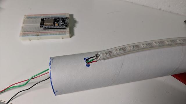
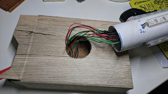
2. Cut WS2812B LED strip into four pieces with 30 LED each. Solder three wires on each WS2812B LED strip; Red for + pin; Black for – pin; Green for data pin. Then, cut small holes on the bottom of the paper tower core. This is used for the wire to go through.
3. Glue four LED strips on the paper tower core with double sided tape and let wires go inside the paper tower core. So we could collect all wires to the base for easier connections.
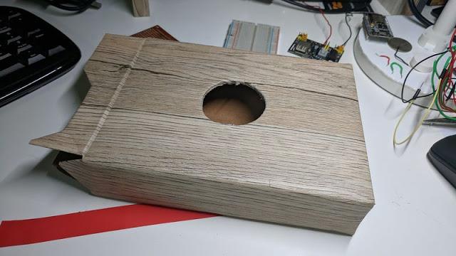
4. Here I used a thicker paper box as the base and cut a hole on the center top. Also, I fill the inside with Styrofoam to make the base more stable. Then, drill a hole that’s roughly the diameter of the paper tower core.
5. Place the paper tower core into the hole of the paper box.
6. To decorate the base, I used wooden color paper sticker to wrap around the paper box. It does look better!
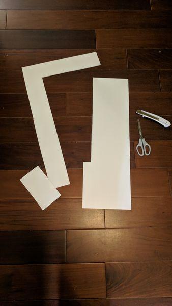
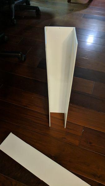
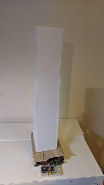
7. Cut white plastic cardboard into equal length that’s roughly longer than the total height of the paper tower core.
8. Glue these white plastic cardboard into a long squared tube as shown.
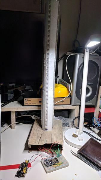
9.Insert the paper tower core with LED strips into the base with all the wires to go through the paper box base.
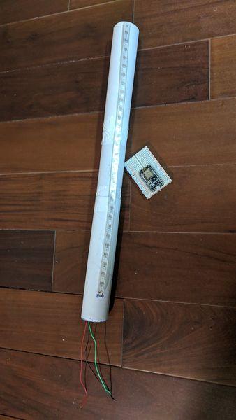
11. Here is the almost completed LED lighting unit
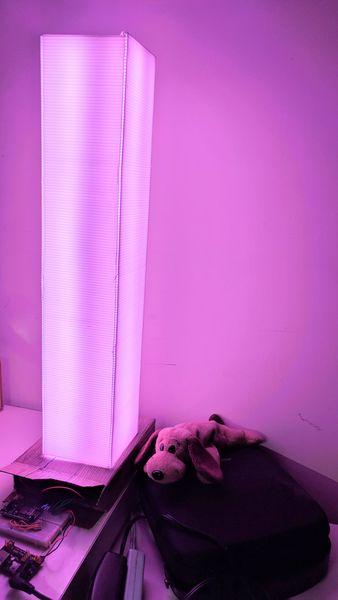
12. Now, place the white plastic square tube on the paper tower core to diffuse the LED colors.
13. Light it up. It looks pretty good!
PS: I reused a 5V/2.4A old power adapter. I think this is bright enough for the LED lighting. Do not use 5V/1A or 5V/1.5A for this project, the light will be incorrect and very dim.
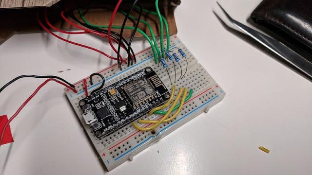
Connection:
This video shows you the detailed connections on NODEMCU and WS2812B LED strips.
Red to 5V+ (total 4 pins from LED strips)
Black to GND (total 4 pins from LED strips)
Green to NODEMCU data pins ((total 4 pins from LED strips; D2,D3,D4,D5)
NodeMCU VIN to 5V+
NodeMCU GND to power Adapter GND (Share GND)
5V/2.4A power adapter to 5V+
5V/2.4A power adapter to GND
1000uF Capacitor parallel with the power adapter (Not in this tutorial, since I haven't purchase this yet :)
Programming codes:
/***************************************************
  Adafruit MQTT Library ESP8266 Adafruit IO SSL/TLS example
  Must use the latest version of ESP8266 Arduino from:
    https://github.com/esp8266/Arduino
  Works great with Adafruit's Huzzah ESP board & Feather
  ---- https://www.adafruit.com/product/2471
  ---- https://www.adafruit.com/products/2821
  Adafruit invests time and resources providing this open source code,
  please support Adafruit and open-source hardware by purchasing
  products from Adafruit!
  Written by Tony DiCola for Adafruit Industries.
  SSL/TLS additions by Todd Treece for Adafruit Industries.
  MIT license, all text above must be included in any redistribution
 ****************************************************/
#include <ESP8266WiFi.h>
#include "Adafruit_MQTT.h"
#include "Adafruit_MQTT_Client.h"

//This line allows one to use NODEMCU pin name, such as D0
#define FASTLED_ESP8266_RAW_PIN_ORDER
#include <FastLED.h>
#include <Wire.h>


// Information about the LED strip itself

#define LED_PIN1     D3
#define LED_PIN2     D4
#define LED_PIN3     D5
#define LED_PIN4     D6
#define COLOR_ORDER GRB
#define CHIPSET     WS2811
#define NUM_LEDS    30
#define BRIGHTNESS  255

CRGB leds[NUM_LEDS];


// FastLED v2.1 provides two color-management controls:
//   (1) color correction settings for each LED strip, and
//   (2) master control of the overall output 'color temperature'
//
// THIS EXAMPLE demonstrates the second, "color temperature" control.
// It shows a simple rainbow animation first with one temperature profile,
// and a few seconds later, with a different temperature profile.
//
// The first pixel of the strip will show the color temperature.
//
// HELPFUL HINTS for "seeing" the effect in this demo:
// * Don't look directly at the LED pixels.  Shine the LEDs aganst
//   a white wall, table, or piece of paper, and look at the reflected light.
//
// * If you watch it for a bit, and then walk away, and then come back
//   to it, you'll probably be able to "see" whether it's currently using
//   the 'redder' or the 'bluer' temperature profile, even not counting
//   the lowest 'indicator' pixel.
//
//
// FastLED provides these pre-conigured incandescent color profiles:
//     Candle, Tungsten40W, Tungsten100W, Halogen, CarbonArc,
//     HighNoonSun, DirectSunlight, OvercastSky, ClearBlueSky,
// FastLED provides these pre-configured gaseous-light color profiles:
//     WarmFluorescent, StandardFluorescent, CoolWhiteFluorescent,
//     FullSpectrumFluorescent, GrowLightFluorescent, BlackLightFluorescent,
//     MercuryVapor, SodiumVapor, MetalHalide, HighPressureSodium,
// FastLED also provides an "Uncorrected temperature" profile
//    UncorrectedTemperature;
#define TEMPERATURE_1 Tungsten100W
#define TEMPERATURE_2 OvercastSky
// How many seconds to show each temperature before switching
#define DISPLAYTIME 20
// How many seconds to show black between switches
#define BLACKTIME   3

// Relay settings
#define relay2Pin D7 //NodeMCU pin D7
#define relay1Pin D8 //NodeMCU pin D8
int relay1Status = 0; //switch of the relay; either 0=off or 1=on
int relay2Status = 0; //switch of the relay; either 0=off or 1=on


/************************* WiFi Access Point *********************************/

#define WLAN_SSID       "Use_your_ssid"
#define WLAN_PASS       "Use_your_wifi_password"

/************************* Adafruit.io Setup *********************************/

#define AIO_SERVER      "io.adafruit.com"
#define AIO_SERVERPORT  8883                   // 8883 for MQTTS sercure, 1883 for non-Secure
#define AIO_USERNAME    "Use_your_user_name"
#define AIO_KEY         "Use_your_own_AIO_key"

/************ Global State (you don't need to change this!) ******************/

// WiFiFlientSecure for SSL/TLS support
WiFiClientSecure client;

//WiFiClient for non-secure
//WiFiClient client;

// Setup the MQTT client class by passing in the WiFi client and MQTT server and login details.
Adafruit_MQTT_Client mqtt(&client, AIO_SERVER, AIO_SERVERPORT, AIO_USERNAME, AIO_KEY);

// io.adafruit.com SHA1 fingerprint
const char* fingerprint = "AD 4B 64 B3 67 40 B5 FC 0E 51 9B BD 25 E9 7F 88 B6 2A A3 5B";

/****************************** Feeds ***************************************/

// Setup a feed called 'test' for publishing.
// Notice MQTT paths for AIO follow the form: <username>/feeds/<feedname>
//Adafruit_MQTT_Publish light_color = Adafruit_MQTT_Publish(&mqtt, AIO_USERNAME "/feeds/light-color");
//Adafruit_MQTT_Publish light_1 = Adafruit_MQTT_Publish(&mqtt, AIO_USERNAME "/feeds/light-1");

/*************************** Sketch Code ************************************/
// Bug workaround for Arduino 1.6.6, it seems to need a function declaration
// for some reason (only affects ESP8266, likely an arduino-builder bug).
void MQTT_connect();
void verifyFingerprint();

//set up two feeds called 'light_1' / 'light_color' for subscribing to changes
Adafruit_MQTT_Subscribe light_1 = Adafruit_MQTT_Subscribe(&mqtt, AIO_USERNAME "/feeds/light-1");
Adafruit_MQTT_Subscribe light_color = Adafruit_MQTT_Subscribe(&mqtt, AIO_USERNAME "/feeds/light-color");

void setup() {
  delay( 3000 ); // power-up safety delay for LED stripe

  Serial.begin(115200);
  delay(10);

  //MQTT connection indication when Blue is on
  pinMode(LED_BUILTIN, OUTPUT);

  // Relay pins
  pinMode(relay1Pin, OUTPUT);
  pinMode(relay2Pin, OUTPUT);

  //LED pins
  pinMode(LED_PIN1, OUTPUT);
  pinMode(LED_PIN2, OUTPUT);
  pinMode(LED_PIN3, OUTPUT);
  pinMode(LED_PIN4, OUTPUT);

  //FastLED declaration
  FastLED.addLeds<CHIPSET, LED_PIN1, COLOR_ORDER>(leds, NUM_LEDS).setCorrection( TypicalLEDStrip );
  FastLED.addLeds<CHIPSET, LED_PIN2, COLOR_ORDER>(leds, NUM_LEDS).setCorrection( TypicalLEDStrip );
  FastLED.addLeds<CHIPSET, LED_PIN3, COLOR_ORDER>(leds, NUM_LEDS).setCorrection( TypicalLEDStrip );
  FastLED.addLeds<CHIPSET, LED_PIN4, COLOR_ORDER>(leds, NUM_LEDS).setCorrection( TypicalLEDStrip );
  FastLED.setBrightness( BRIGHTNESS );

  //Turn on the light to White in the beginning
  Serial.println(F("Connecting Wi-Fi...(Blue)"));
  fill_solid(leds, NUM_LEDS, CRGB::Blue);
  FastLED.show();

  Serial.println(F("Home MQTT Color Light Control System"));

  // Connect to WiFi access point.
  Serial.println(); Serial.println();
  Serial.print("Connecting to ");
  Serial.println(WLAN_SSID);

  WiFi.begin(WLAN_SSID, WLAN_PASS);

  while (WiFi.status() != WL_CONNECTED) {
    delay(500);
    Serial.print(".");
  }
  Serial.println();

  Serial.println("WiFi connected");
  Serial.print("IP address: "); Serial.println(WiFi.localIP());

  // check the fingerprint of io.adafruit.com's SSL cert
  verifyFingerprint();

  //Subscribe to Adafruit Feed!
  mqtt.subscribe(&light_1);
  mqtt.subscribe(&light_color);

  //Turn on the light When io.adafruit.com & MQTT connected
  Serial.println(F("Wi-Fi Connected...(White)"));
  fill_solid(leds, NUM_LEDS, CRGB::White);
  FastLED.show();

}

uint32_t x = 0;

/* This turn on/off relay switch

*/
void switchRelay(int relay, int stat) {

  if (relay == 2) { //this is light-1;
    if (stat == 0) {
      digitalWrite(relay2Pin, LOW);
      relay1Status = 0;
      Serial.println(F("Relay off"));
    }
    if (stat == 1) {
      digitalWrite(relay2Pin, HIGH);
      relay1Status = 1;
      Serial.println(F("Relay on"));
    }
  }
  if (relay == 1) { //this is color-light;
    if (stat == 0) {
      digitalWrite(relay1Pin, LOW);
      relay2Status = 0;
      Serial.println(F("Relay off"));
    }
    if (stat == 1) {
      digitalWrite(relay1Pin, HIGH);
      relay2Status = 1;
      Serial.println(F("Relay on"));
    }
  }
}

void loop() {

  String feed_lastread; //This is the String of effect name read from Adafruit.IO
  // Ensure the connection to the MQTT server is alive (this will make the first
  // connection and automatically reconnect when disconnected).  See the MQTT_connect
  // function definition further below.
  MQTT_connect();


  Adafruit_MQTT_Subscribe *subscription;
  while ((subscription = mqtt.readSubscription(1000))) {


    if (subscription == &light_1) {

      Serial.print(F("Light-1:"));
      Serial.println((char *)light_1.lastread);
      feed_lastread = (char *)light_1.lastread;
      feed_lastread.trim(); //
      // Serial.println("Light 1:" + feed_lastread); //for verifying the varialble
      // *** NOTICE: adafruit.io publishes the data as strings, not numbers!!!
      if (feed_lastread == "ON") {
        switchRelay(2, 1);
      }
      if (feed_lastread == "OFF") {
        switchRelay(2, 0);
      }
    }


    if (subscription == &light_color) {
      Serial.print(F("Color-Light:"));
      Serial.println((char *)light_color.lastread);
      feed_lastread = (char *)light_color.lastread;
      feed_lastread.trim(); //
      // Serial.println("Color Light:" + feed_lastread); //for verifying the variable
      // *** NOTICE: adafruit.io publishes the data as strings, not numbers!!!
      if (feed_lastread == "ON") {
        switchRelay(1, 1);
      } else if (feed_lastread == "OFF") {
        switchRelay(1, 0);
      } else {
        //if (relay2Status == 1 ) { //Only send color light commands when Color Light is on
        colorEffectFunction(feed_lastread);
        //}
      }
    }

  } //while MQTT got message loop

  /*
    switchRelay();
    Serial.print(F("\nSwitch is:"));
    if (relay1Status == 1) {
    Serial.print(F("On"));
    } else {
    Serial.print(F("Off"));
    }

    // Now we can publish stuff!
    Serial.print(F("\nSending val "));
    Serial.print(x);
    Serial.print(F(" to Relay1 feed..."));
    if (! Relay1.publish(x++)) {
    Serial.println(F("Failed"));
    } else {
    Serial.println(F("OK!"));
    }

    // Now we can publish stuff!
    Serial.print(F("\nSending val "));
    Serial.print(x);
    Serial.print(F(" to Relay2 feed..."));
    if (! Relay2.publish(x)) {
    Serial.println(F("Failed"));
    } else {
    Serial.println(F("OK!"));
    }

    // wait a couple seconds to avoid rate limit
    delay(5000);
  */

}
/*
   This function show the color light

  Control multiple WS2812 strips easily!
  https://github.com/FastLED/FastLED/wiki/Multiple-Controller-Examples

  FastLED All effects in one script
  https://www.tweaking4all.com/hardware/arduino/arduino-all-ledstrip-effects-in-one/

  Take this to complete your "Google Home" project
  First example to show you the basics about FastLED: https://www.tweaking4all.com/hardware/arduino/adruino-led-strip-effects/

*/
void colorEffectFunction(String colorVariant) {

  Serial.print(F("Color effect:"));

  if (colorVariant == "rainbow") {
    static uint8_t starthue = 0;
    Serial.println(F("Rainbow"));
    fill_rainbow( leds, NUM_LEDS, --starthue, 20);
    FastLED.show();
  }
  if (colorVariant == "candle") {
    Serial.println(F("Candle"));
    fill_solid(leds, NUM_LEDS, Candle);
    FastLED.show();
  }
  if (colorVariant == "red") {
    Serial.println(F("Red"));
    fill_solid(leds, NUM_LEDS, CRGB::OrangeRed);
    FastLED.show();
  }
  if (colorVariant == "green") {
    Serial.println(F("Green"));
    fill_solid(leds, NUM_LEDS, CRGB::Green);
    FastLED.show();
  }
  if (colorVariant == "blue") {
    Serial.println(F("Blue"));
    fill_solid(leds, NUM_LEDS, CRGB::Blue);
    FastLED.show();

  }
  if (colorVariant == "yellow") {
    Serial.println(F("Yellow"));
    fill_solid(leds, NUM_LEDS, CRGB::Yellow);
    FastLED.show();
  }
  if (colorVariant == "gold") {
    Serial.println(F("Gold"));
    fill_solid(leds, NUM_LEDS, CRGB::Gold);
    FastLED.show();
  }
  if (colorVariant == "orange") {
    Serial.println(F("Orange"));
    fill_solid(leds, NUM_LEDS, CRGB::Orange);
    FastLED.show();
  }
  if (colorVariant == "White") {
    Serial.println(F("White"));
    fill_solid(leds, NUM_LEDS, CRGB::White);
    FastLED.show();
  }
  if (colorVariant == "purple") {
    Serial.println(F("Std. Fluorescent"));
    fill_solid(leds, NUM_LEDS, CRGB::Purple);
    FastLED.show();
  }

}


void verifyFingerprint() {

  const char* host = AIO_SERVER;

  Serial.print("Connecting to ");
  Serial.println(host);

  if (! client.connect(host, AIO_SERVERPORT)) {
    Serial.println("Connection failed. Halting execution.");
    while (1);
  }


  //  if (client.verify(fingerprint, host)) {
  //    Serial.println("Connection secure.");
  //  } else {
  //    Serial.println("Connection insecure! Halting execution.");
  //    while(1);
  //  }

}

// Function to connect and reconnect as necessary to the MQTT server.
// Should be called in the loop function and it will take care if connecting.
void MQTT_connect() {
  int8_t ret;

  // Stop if already connected.
  if (mqtt.connected()) {
    return;
  }

  Serial.print("Connecting to MQTT... ");

  uint8_t retries = 30;
  while ((ret = mqtt.connect()) != 0) { // connect will return 0 for connected
    Serial.println(mqtt.connectErrorString(ret));
    Serial.println("Retrying MQTT connection in 5 seconds...");
    mqtt.disconnect();
    delay(5000);  // wait 5 seconds
    retries--;
    if (retries == 0) {
      // basically die and wait for WDT to reset me
      while (1);
    }
  }

  Serial.println("MQTT Connected!");
  //Turn on Blue LED to indicate it's connected.
  digitalWrite(LED_BUILTIN, HIGH);
}
使用聲控命令說“set color lighting”+顏色來改變燈光顏色。
例如:如果您說“set color lighting red”,則照明將從當前顏色更改為“紅色”, 非常有趣實用!
雖然上次用聲音打開/關閉燈開關在日常生活中也非常實用,但它在某種程度上並不那麼好玩。 在本教學中,您將能夠使用語音更改RGB燈光顏色。