2019/11/03

Arduino ESP32-CAM for video stream notebook

Preface

Recently, I acquired an ESP32-CAM Wi-Fi + Bluetooth + OV2640 camera module. My first intent was to learn how to use new Arduino ESP32 compatible modules. Then, I quickly found out with ESP3D that I could use ESP32-CAM to monitor and control my Ender 3 Pro 3D printer remotely, what a bonus!

This is my personal notebook and you are welcome to follow along and hope it might actually help!


Goal for this post

Config ESP32-CAM to use it as a web server to stream videos.
Long term goal is to use ESP32-CAM and ESP3D to make a 3D printer remote monitoring device.


ESP32-CAM Spec

  • ESP32 32bit dual core 600 DIMPS
  • 520KB SRAM + 4MB PSRAM
  • I/O: UART, SPI, I2C, PWM
  • MicroSD: Up to 4GB
  • Baud Rate: Default 115200 bps
  • Photo format: JPEG( OV2640 only), BMP, GRAYSCALE
  • Wi-Fi: 802.11 b/g/n/d/e/i/k/r 
  • Bluetooth: V4.2 BR/EDR and BLE
  • Power: 5V/2A
  • Built-in flash light
  • Camera module: OV2640, 200 Mega pixels


Schematic 

Since there is no USB on ESP32, I use a CP210x USB to UART bridge to upload.
Or, you can use a FTDI USB to UART bridge to upload sketches.

IMPORTANT NOTICE:
  • Enable ESP32 upload mode: Connect ESP32 IO0  to GND
  • ESP32 Normal operation mode: Remove ESP32  IO0 to GND connection
  • Power: must connect ESP32 VCC (5V) to VCC 
  • Wiring:
    • ESP32 GND <-> ESP32 IO0 (Upload only, remove for normal operation)
    • ESP32 GND <-> CP210x GND
    • ESP32 VCC(5V) <-> CP210x VCC
    • ESP32 U0R <-> CP210x TXD
    • ESP32 U0T <-> CP210x RXD

Then, connect
  • Camera module to ESP32-CAM
  • Then, plug CP210x dongle to PC USB port


Download Arduino IDE version greater than V1.8.9

Version 1.8.9 or above is required for ESP32-CAM. Please visit Arduino official website to download the version, if needed.

After installation follow the steps below:

1. Click File -> Preferences


2. Click the small square at end of Additional Boards Manager URL:

  • Enter: https://dl.espressif.com/dl/package_esp32_index.json
  • This URL allows Arduino IDE to download ESP32 package. If you had two URLs, separate them with a ',' common. Click OK to exit. Usually, the first one is for ESP8266 related package.


3. Select Boards Manager to install ESP32 library


4. Type 'ESP32'  in the search box and hit enter

  • Board manager will start to search ESP32 library. When 'esp32 by Espressif Systems' is found, click Install. 


5. Wait till the installing process finish


6. Click 'Close' when ESP32 package is INSTALLED


7. From Arduino IDE, Tools, select Board, and select "ESP32 Wrover Module"

  • Also, change Upload Speed to "115200", the ESP32 default baud rate. (No screenshot shown here)


8. From Tools, select Partition Scheme, select Huge APP (3MP No OTA/1MB SPIFFS)

  • Due to ESP32-CAM sketch size is quite large, select this item is necessary to keep program memory at it's maximum for ESP32

  • By now, Arduino IDE setting is completed.


9. (Optional) Only needed if you do not have FTDI/CP210x USB drivers in PC/Mac


10. Connect CP210x USB dongle to PC USB port

  • From Arduino IDE, select "Toos"->"Monitor"
  • Change baud rate to 115200 to match default ESP32 baud rate setting


11. Load a sketch from File->Examples->WiFi->WiFiScan

  • Load WiFiScan sketch to ensure the hardware and software /IDE settings are correct.

12. Upload the sketch 

  • Just click the small arrow circled below to upload to ESP32


If you encountered ERROR: Upload failed: "Timed out waiting for packet header"

  • CAUSE: This error indicates ESP32 IO0 didn't connect to GND. This connection is needed enable ESP32 upload mode.
  • Push reset button: when you see ....._____....._____.....____


After the connection made from ESP32 IO0 to GND and the uploading worked. 

  • Message window shows "Writing at .......100%" indicates the upload completed!


13. Check out serial monitor for messages

  • In this step, ESP32 will scan available AP nearby and show them in the monitor.
  • If you encountered ERROR: "waiting for download" message!  This error indicates that you need to remove ESP32 IO0 Pin to GND pin (Mentioned above that this connection must be removed for ESP32 to work properly!)


After remove the connection, and push reset, ESP32 found few Wi-Fi AP nearby


14. Load CameraWebServer sketch

  • It's time to test out the ESP32 web server and stream videos
  • From "File"->"Examples"->"ESP32"->"Camera"->CameraWebServer


15. Change Wi-Fi AP SSID and Password to match your own Wi-FI SSID/Password


16. Change the camera model to AI_THINKER

  • The camera module is the in the package came with ESP32. So I selected the default "AI_THINKER"


17. Get web server IP address

  • If everything goes well, the camera IP address would show on the serial monitor
  • Copy the IP address shown


18. Open a browser and type the IP address specified above

  • The screen below shows ESP32 web server is running successfully
  • Select the resolution on the top
  • Click Start Stream and the video will show on the right hand side


19. Real-time camera video stream in browser

  • If you like, you could change the resolution and play around many OV2640 parameters.
  • For the resolution, the larger the resolution, the fewer the frame rates.


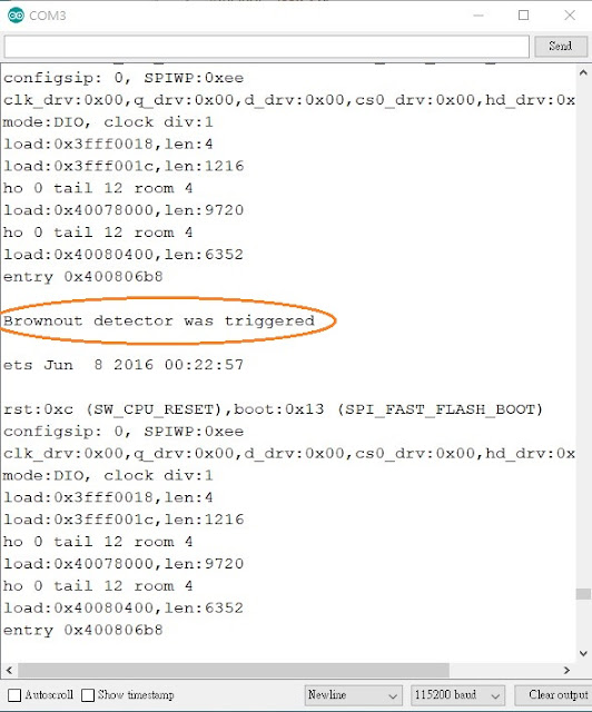
If you encountered ERROR message "Brownout detector was triggered", many articles indicated causes could be:
  • Poor quality USB cable
  • USB cable is too long
  • Or not enough power to USB port


After I changed to dedicated USB port to connect ESP32, the video came back alright and running for a while without the error messages.

What's Next

After 2-3 hours, the config/setting on ESP32 was done. Next step is to install ESP3D to remote monitoring my 3D printer.  Until next time, see you!


References:


======== 中 文 版 ==========

前言

最近,我購買了ESP32-CAM Wi-Fi +藍牙+ OV2640相機模組。 本來是打算學習如何使用新的Arduino ESP32 相容模組。 後來我發現它可以搭配ESP3D,用ESP32-CAM遠程監視和控制Ender 3 Pro 3D打印機,這真是太好了!

這是我的個人筆記本,歡迎您繼續閱讀並希望它能對您有所幫助!


本篇目的

設定及使用ESP32-CAM以將其用作網絡服務器以及串流視訊。
長期目標是使用ESP32-CAM和ESP3D製作3D印表機遠端監控及控制設備。


ESP32-CAM 規格

  • ESP32 32bit dual core 600 DIMPS
  • 520KB SRAM + 4MB PSRAM
  • I/O: UART, SPI, I2C, PWM
  • MicroSD: Up to 4GB
  • Baud Rate: Default 115200 bps
  • Photo format: JPEG( OV2640 only), BMP, GRAYSCALE
  • Wi-Fi: 802.11 b/g/n/d/e/i/k/r 
  • Bluetooth: V4.2 BR/EDR and BLE
  • Power: 5V/2A
  • Built-in flash light
  • Camera module: OV2640, 200 Mega pixels


接線方式

由於ESP32上沒有USB孔,因此我使用CP210x USB至UART轉接器進行上傳。
您可以使用FTDI USB至UART來上傳程式。

請注意:
  • 啟用ESP32上載模式:將ESP32 IO0連接到GND
  • ESP32正常運行模式:拔開ESP32 IO0到GND的連接
  • 電源:必須將ESP32 VCC(5V)連接到VCC
  • 連接:
    • ESP32 GND <-> ESP32 IO0 (只有上傳需要連接!)
    • ESP32 GND <-> CP210x GND
    • ESP32 VCC(5V) <-> CP210x VCC
    • ESP32 U0R <-> CP210x TXD
    • ESP32 U0T <-> CP210x RXD

接線完成後,把模組及CP210x接到 PC USB 插槽
  • 相機模組接上 ESP32-CAM
  • 把CP210x 接到 PC USB 孔


下載Arduino IDE版本大於V1.8.9版本

ESP32-CAM需要版本1.8.9或更高版本。 如果沒有此版本,請到Arduino官方網站下載版本。
安裝後,請執行以下步驟:

1. 點擊文件 -> 偏好


2. 點擊Additional board manager URL後面的小方框:

  • 輸入:https://dl.espressif.com/dl/package_esp32_index.json 按 OK
  • 這可以讓 Arduino IDE下載ESP32相關程式。 如果您有兩個URL,請用一個',' 將它們分開,再按 OK。 一般來說,第一個是用於ESP8266相關程式。


3. 選擇Boards Manager來安裝ESP32版子相關程式


4. 在搜索框中輸入“ ESP32”,然後按Enter

  • Board Manager 將開始搜索ESP32程式庫。 當找到“ Espressif Systems esp32”時,點擊“安裝”。


5. 等到安裝過程完成


6. 安裝ESP32程式後,點擊“Close”。

7. 從Arduino IDE中,選擇 Tools,選擇 Board,然後選擇“ ESP32 Wrover Module”

  • 另外,將“上傳速度”更改為ESP32默認傳輸速率“ 115200”。 (這張沒有截圖)


8. 從“Tools”中,選擇“Partition Scheme”,然後選擇“Huge App”(3MP No OTA / 1MB SPIFFS)
  • 由於ESP32-CAM的程式很大,因此請選擇此項目以將程式憶空間保持為ESP32的最大容量

  • 至這裡,Arduino IDE設定完成。


9. (選項)只有你確認 PC / Mac中沒有FTDI / CP210x USB驅動程式時才需要做


10.將CP210x USB 連接到PC USB

  • 在Arduino IDE中,選擇 Tools,  Serial Monitor
  • 傳輸速率更改為115200以搭配默認ESP32認傳輸速率


11. 打開測試程式 File, Examples, WiFi, WiFiScan

  • 打開WiFiScan程式來測試 硬體及軟體設置是否正確

12.  上傳程式到 ESP32

  • 只需點選下面圓圈的小箭頭,即可上傳到ESP32


如果遇到錯誤, 上傳失敗:  "Timed out waiting for packet header"

  • 原因:此錯誤表示ESP32 IO0未連接到GND。 上面有提到過了, ESP32上載模式需要此連接!。
  • 當你看到 ....._____....._____.....____ 訊息時, 按一下 ESP32 Reset 鈕!


把ESP32 IO0到GND的連接成功後,就能上傳成功。

  • Serial port 顯示“writing at 0x00000800....... 100%” 表示上傳已完成!


13. 查看Serial Monitor內容

  • 在這裡,ESP32將掃描附近的可用Wi-FI AP並將其顯示
  • 如果遇到錯誤:“Waiting for download! 該錯誤表明您需要移除ESP32的IO0至GND連線(上面提到必須移除此連接才能使ESP32正常工作!)


把ESP32的IO0至GND連線拔掉後, ESP32在附近發現了幾個Wi-Fi AP


14.加載CameraWebServer草圖

  • 現在來測試ESP32 Web服務器及試試串流傳輸影像
  • 從“文件, File, Example, ESP32, Camera, then 點選 CameraWebServer


15. 更改Wi-Fi AP SSID和密碼以成為您自己家裡的Wi-FI SSID /密碼


16. 將相機型號更改為AI_THINKER

  • 相機模組是ESP32隨附的相機模組, 所以選擇了內定的“ AI_THINKER”


17. 取得 ESP32 IP 地址

  • 如果一切順利,相機的IP地址將顯示在 Serial Monitor 上面
  • 複製顯示的IP地址


18. 打開瀏覽器並輸入上面指定的IP地址

  • 以下屏幕顯示ESP32 Web服務器運行成功
  • 選擇頂部的解析度
  • 點擊"Start to stream",開始串流, 影像將顯示在右側


19. 瀏覽器中的實時攝像機串流

  • 你可以更改解析度, 並且更改OV2640不同參數。
  • 解析度越大,每秒顯示的幀率越少。


如果您遇到錯誤訊息“Brownout detector was triggered”,則表明原因的許多文章可能是:
  • USB電線品質不良
  • USB電線太長
  • USB端電量不足


我改用專用的USB連接ESP32之後,視訊又恢復正常並運行了一段時間,就再也沒有出現錯誤訊息。


接下來?

經過2-3小時後在ESP32上的配置/設置已完成也測試成功。 下一步是安裝ESP3D以遠程監視我的3D打印機! See you next time!

2019/07/21

3D Printer Dampening Feet Noise Test

10 times less noise!


I just purchased my Creality Ender 3 Pro and after modified the HW(will write what I have modified later) and turning, turning, and more turning. It finally worked well after a month.

Many people in the Facebook group discussing what parts could self-print to upgrade.  One of them was the dampening feet to reduce noise. I tested the noise level in dB with Google Science Journal APP. The test duration was 31 seconds with PLA, 0.2 layer high, 100% infill.  Please see the results below.

 My Testing Results

In my test, Dampening feet reduced about 11 dB* about 10 times less noise! This is quite amazing!

However, few people in Facebook groups mentioned that there might be other disadvantages, such as wobbling when printing tall objects and these feet might broken easily.  

* A sound 10 times more powerful is 10 dB.
* A sound 100 times more powerful than near total silence is 20 dB.
Source: How stuff works


Print with Dampening Feet

Test Duration: 31 seconds
Average: 22 dB
Max: 37 dB
Google Science Journal App recorded the noise level


I have printed the same Dampening feet to get the more accurate noise level.


See the printing of a Damping feet in action (With Dampening feet)


Print without Dampening Feet

Test Duration: 31 seconds
Average: 30 dB
Max: 48 dB
Google Science Journal App recorded the noise level

The noise was recorded during printing the Dampening Feet.

Download .STL files

All the .STL file can be downloaded from Thingiverse.com
Original design was from Ender 3 Damping Feet by redmaxver

The one I downloaded  and tested was Ender 3 Complete Dampening Feet by rhin0xx
rhin0xx combined all 8 components together saved me some troubles.

The End

----------------中文版----------------------

大減10倍音量

我剛剛在對岸淘了一台 Creality Ender 3s (和3 Pro是同一機種),參考了網路上建議修改了一些東西(我之後會寫一篇我改了那裡的文章)之後就一直調整,換零件,又換零件,一直不斷的調整。大約一個月之後,它終可以正常的列印了。

Facebook上有許多人都在討論哪些部分可以自行3D列印來升級這台印表機。其中一個討論很多的是減震腳,它可以減少噪音。我用 Google Science Journal APP 測試持續時間31秒再觀查它的噪音值 dB。我是用原廠的 PLA, 0.2 層高, 100% infill。測試結果請參閱下面說明。

我的測試結果

我的測試結果顯示,減震腳減少了大約11分貝(dB, 減了10倍音量)*  !這讓我太訝異了!
不過,Facebook群組中也有不少人提到其他可能缺點,例如在打印較高的物件時,機體可能會搖晃影響到列印結果,還有這些減震腳也可能很容易斷裂。

* 10倍的音量是10分貝(dB)
* 100倍的音量是20分貝(dB)
資料來源: How stuff works

加減震腳裂印測試

測試時間長度: 31秒
平均噪音: 22分貝 dB
最大噪音: 37分貝 dB
Google Science Journal App 來記錄噪音值

加減震腳照片


我列印同一個物件來測試 加減震腳噪音
來讓測結果能更正確


 加減震腳的列印影片 


未加減震腳裂印測試

測試時間長度: 31秒
平均噪音: 30分貝 dB
最大噪音: 48分貝 dB
Google Science Journal App 來記錄噪音值

上方的噪音值是列印減震腳時錄製的

下載 .STL 檔案

全部的 .STL 檔案均由 Thingiverse.com 下載
原始的設計者 Ender 3 Damping Feet by redmaxver

我下載及列印的是 Ender 3 Complete Dampening Feet 由 rhin0xx 所修改的
rhin0xx 把 8 個物件全部放在同一個檔案內,比較方便列印。

全文完


2019/05/25

Light Tracking Gimbal


Preface

Based on my previous project (Joystick Control Gimbal), I slightly modified it into a Light Tracking device.  It took me about two days to fine-tune the Light Tracking Gimbal to move smoothly and hold its position while light source is not moving.

Goal of this tutorial

Let's see the video below to see what's the final result of this tutorial.


Gimbal Panel Area

There are Top Left, Top Right, Bottom Left, and Bottom Right.
In each area, there is a light sensor.


Programming Logic:

  1. Get reading from 4 photo sensors 
    • I sample each sensor 10 times and then get the average value to ensure the readings are more stable
  2. Get average of each side
    • Top side value = (Top left + Top right) / 2
    • Bottom side value = (Bottom left + Bottom right) / 2
    • Left side value = (Top left + Bottom left ) / 2
    • Right side value = (Top right + Bottom right ) / 2
  3. Compare all four sides to see which side has bigger value
  4. Move the servo towards the biggest side among four side
  5. Tolerance variable is in control whether to move or not based on how much differences among four sides. If reading values from four sides were within the range of 100, then keep the Gimbal static(Hold it's position) (default value = 100)
Tolerance variable is the most important variable to ensure the Gimbal holds its position when four light sensors get values within the defined tolerance!

Component Needed for this project

  • Arduino Nano * 1
  • SG90 Servo * 2
  • Light sensors * 4
  • 10K Resistors * 4
  • Prontoboard * 1
  • Many jump wires
  • Extra long wires for photo sensor connect * 4
  • Heat shrink tube 2cm * 4

Tools Needed

  • Soldering gun * 1
  • Diagonal cutting pliers * 1
  • Screw driver * 1
  • Few screws * 10
  • Double sided tape

Schematic: (I use fritzing for this schematic)


Program Code:

*************************************************************
*** Please click subscribe my YouTube Channel before use the code 
*** There is no restriction, but I would be really appreciated 
*** if you did. Thank you!  **************************************************************

*************************************************************
*** 在 Copy 底下程式碼之前,請按下底下按鈕,訂閱我的 YouTube 頻道! 
*** 雖沒有強制規定,不過如果你有訂閱的話,非常感謝你! 
**************************************************************
/**
   Author: Kevin Chen AKA Stonez56 
   My Blog to see more tutorials: https://stonez56.blogspot.com
   Date: 2019/05/11 The day before mother's day

    Program function flow
   1. Reading four light sensor values
   2. Average top two(Top left, Top right), bottom two(Bottom left, Bottom right)
   3. Average left two(Top left, Bottom left), right two (Top right, Bottom right)
   4. Compare 4 averaged value and make servo mave toward the biggest number side
   
   v0 Light traking Gimbal base to get readings
   v1 Write servo code in and move servo accordingly

                    |
         Top left   |     Top right
   -----------------+----------------------
     Bottom left   |  Bottom right
                    |
*/
#include <Servo.h>
Servo servo1_x;
Servo servo2_y;

//Light Sensor Pin definitions
const uint8_t  light_top_left_PIN = A6;
const uint8_t  light_bottom_left_PIN = A5;
const uint8_t  light_top_rigth_PIN = A2;
const uint8_t  light_bottom_right_PIN = A1;
//Potentiometer pin
const  int potPIN = A0;
//Servo pins
const int servo1_x_pin = 2;
const int servo2_y_pin = 4;


//User define variables
// Gimbal movement tolerance 50~255
byte gimbal_movement_tolerance = 100;
//Photo sensor max reading times for average (for more accuracy)
byte max_reading = 10;
// define original servo angle
uint8_t originalAngle = 92;
uint8_t x_last = originalAngle;  // X last postion
uint8_t y_last = originalAngle; // Y last postion
uint8_t moveSpeed = 10;  //How fast show this Servo move
uint8_t maxSpeed = 50; //Max speed
uint8_t minSpeed = 1;
uint8_t y_minAngle = 1;  //Mimum angle
uint8_t y_maxAngle = 180;  //Maximum angle
uint8_t x_minAngle = 90;  //Mimum angle
uint8_t x_maxAngle = 180;  //Maximum angle

void setup() {
  Serial.begin(57600);

  pinMode(light_top_left_PIN, INPUT);
  pinMode(light_bottom_left_PIN, INPUT);
  pinMode(light_top_rigth_PIN, INPUT);
  pinMode(light_bottom_right_PIN, INPUT);

  servo1_x.attach(servo1_x_pin);
  servo1_x.write(originalAngle); //move servo to defined angle
  servo2_y.attach(servo2_y_pin);
  servo2_y.write(originalAngle); //move servo to defined angle

  pinMode(LED_BUILTIN, OUTPUT);
  digitalWrite(LED_BUILTIN, LOW);

}

void loop() {
  char moveTowards = ' ';


  int potValue = analogRead(potPIN);
  Serial.print(F("potValue: "));
  Serial.println(potValue);
  moveSpeed = map(potValue, 0, 500, minSpeed, maxSpeed);
  Serial.print(F("moveSpeed: "));
  Serial.println(moveSpeed);
  moveTowards = getFacingToward(); //find out which side to move


//  Serial.print(F("moveTowards: "));
//  Serial.println(moveTowards);
  moveServo(moveTowards);

  delay(80);
}

void moveServo(char moveTowards) {


  //previous position were stored in x_last, y_last
  switch (moveTowards) {
    case 'T': //Move towards top
      if (x_last - moveSpeed < x_minAngle) {
        x_last = x_minAngle;
        servo1_x.write(x_last);
      } else {
        x_last -= moveSpeed;
        servo1_x.write(x_last);
      }
      break;
    case 'B': //Move towards bottom
      if (x_last + moveSpeed > x_maxAngle) {
        x_last = x_maxAngle;
        servo1_x.write(x_last);
      } else {
        x_last += moveSpeed;
        servo1_x.write(x_last);
      }
      break;
    case 'L': //Move towards left
      if (y_last - moveSpeed < y_minAngle) {
        y_last = y_minAngle;
        servo2_y.write(y_last);
      } else {
        y_last -= moveSpeed;
        servo2_y.write(y_last);
      }
      break;
    case 'R':
      if (y_last + moveSpeed > y_maxAngle) {
        y_last = y_maxAngle;
        servo2_y.write(y_last);
      } else {
        y_last += moveSpeed;
        servo2_y.write(y_last);
      }
      break;
    default:
      //Don't move servo
      break;
  }

}

/**
   This fuction get reading max_reading times and return average
   if it sees an 0, it will skip it
*/
int averageReading(int PIN, byte max_reading) {
  int total = 0;
  int current = 0;

  for (byte i = 0; i <= max_reading; i++) {
    current = analogRead(PIN);
    if (current == 0) {
      current = analogRead(PIN);
    }
    total += current;
  }

  return total / (max_reading);
}

/**


   Parameters: N/A
   Return: char; T, B, R, L to indicate the moving directoin
                       '-' means not moving at all
*/
char getFacingToward() {
  //1. Read each pin max_reading times

  int top_left = averageReading(light_top_left_PIN, max_reading);
  int bottom_left = averageReading(light_bottom_left_PIN, max_reading);
  int top_right = averageReading(light_top_rigth_PIN, max_reading);
  int bottom_right = averageReading(light_bottom_right_PIN, max_reading * 3);

  //Show photo sensor readings...
  Serial.print(F("Top left-A6: "));
  Serial.println(top_left);
  Serial.print(F("Bottom left-A5: "));
  Serial.println(bottom_left);
  Serial.print(F("Top right-A2: "));
  Serial.println(top_right);
  Serial.print(F("Bottom rightA1: "));
  Serial.println(bottom_right);

  //2. Get max value sides(two averaged, see above)
  byte go_direction[4] = {0, 0, 0, 0};
  int toward[4] = {0, 0, 0, 0}; //Top, Bottom, Left, Right
  toward[0] = (top_left + top_right) / 2 ;
  toward[1] = (bottom_left + bottom_right) / 2 ;
  toward[2] = (top_left + bottom_left) / 2;
  toward[3] = (top_right + bottom_right) / 2;

  //3. Add all side and average,
  //    if each side is within the tolerance then don't move Gimbal
  //    average = toward[0] +...toward[3]
  //    average - toward[0] .... toward[3], if all within gimbal_movement_tolerance, then no move
  int total_toward = 0;
  total_toward += toward[0];
  total_toward += toward[1];
  total_toward += toward[2];
  total_toward += toward[3];
  //get average
  int total_average = total_toward / 4; //4 sides
  Serial.print(F("total_average:"));
  Serial.println(total_average);
  //    if each side is within the tolerance then don't move Gimbal
  boolean shouldMove = false;
  //else move the gimbal
  if (total_average - toward[0] > gimbal_movement_tolerance) shouldMove = true;
  if (total_average - toward[1] > gimbal_movement_tolerance) shouldMove = true;
  if (total_average - toward[2] > gimbal_movement_tolerance) shouldMove = true;
  if (total_average - toward[3] > gimbal_movement_tolerance) shouldMove = true;

  Serial.print(F("toward 0 TOP : "));
  Serial.println(toward[0]);
  Serial.print(F("toward 1 BOTTOM: "));
  Serial.println(toward[1]);
  Serial.print(F("toward 2 LEFT: "));
  Serial.println(toward[2]);
  Serial.print(F("toward 3 RIGHT: "));
  Serial.println(toward[3]);

  //Find the biggest number to decide which side to go,
  // but if four values are quite similar, send '-' back to indicate not moving
  char facing = ' ' ;
  if (shouldMove) {
    int max_ = 0;
    if (toward[0] > max_) {
      max_ = toward[0];
      facing = 'T';
    }
    if (toward[1] > max_) {
      max_ = toward[1];
      facing = 'B';
    }
    if (toward[2] > max_) {
      max_ = toward[2];
      facing = 'L';
    }
    if (toward[3] > max_) {
      max_ = toward[3];
      facing = 'R';
    }
  } else {
    facing = '-'; //no need to move
  }
  //  Serial.print(F("shouldMove: "));
  //  Serial.println(shouldMove);
  return facing;
}


References:

  1. Serveo Example: https://www.instructables.com/id/4-Simple-Servo-Project-with-Arduino/ 
  2. Light Sensor Example: https://maker.pro/arduino/tutorial/how-to-use-an-ldr-sensor-with-arduino 
  3. 3D Gimbal base model: https://www.thingiverse.com/thing:2892903
    You probably need slight modification to this model to be able to fix the base... I did
====================THE END============

中文版


前言

根據我之前做的專案(Arduino 用搖桿控制的雙向轉軸的平台),我稍微將它修改為一個光源追蹤裝置。 主要的時間是花在微調在雲台伺服器的控制上,以便它光源不動的情況下,平穩移動並保持其位置。

專案目標

讓我們看一下下面的成果影片,看看本次教學的最終成果:


雲台分區

分為左上角,右上角,左下角,右下角,每一個分區內,各有一顆光敏電阻。


程式邏輯

  1. 從4個光敏電阻讀取訊號數值:
    • 為了得到了更穩定的數值,每個光敏電阻採樣10次,然後取得到平均值。
  2. 取得到每一方向的平均值
    • 上方值=(左上角+右上角)/ 2
    • 下方值=(左下角+右下角)/ 2
    • 左邊值=(左上角+左下角)/ 2
    • 右邊值=(右上角+右下角)/ 2
  3. 比較所有四個方向面,找出更大的值的方向
  4. 將伺服機雲台朝向向大的值方向移動
  5. Tolerance variable 根據四邊之間的差異來控制是否移動。如果四個方向的值大小在 100以內,則伺服機雲台保持不動。(默認值= 100)

所需零件

  • Arduino Nano * 1
  • SG90 伺服馬達 * 2
  • 光敏電阻 * 4
  • 10K 電阻* 4
  • 洞洞板 * 1
  • 許多單蕊線
  • 稍長一些的單蕊線(接光敏電阻用) * 4
  • 熱縮套管 2cm * 4

所需工具

  • 焊鎗工具 * 1
  • 斜口鉗 * 1
  • 縲絲刀 * 1
  • 小縲絲 * 10
  • 雙面膠

線路圖: (我是用 fritzing 工具製作)


程式碼:

請參考英文版上方。

參考資料:

  1. 伺服器: https://www.instructables.com/id/4-Simple-Servo-Project-with-Arduino/ 
  2. 光敏電阻: https://maker.pro/arduino/tutorial/how-to-use-an-ldr-sensor-with-arduino 
  3. 3D 雲台模型: https://www.thingiverse.com/thing:2892903
    個雲台的底座螺絲孔過大,導致 SG90 所附螺絲無法直接鎖緊。要請高手出來修改一下! 

全文完

2019/05/04

A Pan Tilt Gimbal w/ Joystick


In this Arduino tutorial, I will show you how to make A Pan Titl Gimbal with Joystick; plus speed control.  It's quite simple.

This Gimbal base is controlled by the joystick and the potentiometer is used to control how fast the SG90 servo would move.

3D printed Gimbal


Schematic:


In the video, as I turn the potentiometer, the Serial port shows the speed is increased to 9.  You will see the Gimbal base is moving must faster. Also, this video shows you how fast the Gimbal is moving based on the potentiometer value.

Watch the Video:


 Components: 

  •  One Arduino Nano 
  •  One Joystick module 
  •  One Potentiometer 
  •  Two SG90 servo 
  •  3D printed Gimbal base

Wire Connections:

  •  Connect joystick GND, 5V, VRX to A4, VRX to A3 and SW to D6 pins to Arduino.
  •  Connect 1st SG90 servo VCC to 5V, D2, and GND to Arduino 
  •  Connect 2nd SG90 servo VCC to 5V, D4, and GND to Arduino 
  •  Connect potentiometer VCC to 5V, A0, and GND to Arduino 

That's it! I hope you enjoy this tutorial, Have fun!
I'm thinking to extend this project to .... Light tracing Gimbal base, good idea?

Maybe you will be interested in my other projects:


References:


 Source codes:

*************************************************************
*** Please click subscribe my YouTube Channel before use the code 
*** There is no restriction, but I would be really appreciated 
*** if you did. Thank you!  **************************************************************

*************************************************************
*** 在 Copy 底下程式碼之前,請按下底下按鈕,訂閱我的 YouTube 頻道! 
*** 雖沒有強制規定,不過如果你有訂閱的話,非常感謝你! 
**************************************************************

/**
  2019-04-07 V0.4 by Stonez56

  Code from: https://stonez56.blogspot.com

  v0.4 Fix a bug to allow servos to reach the max limited angle
  v0.3 Added potentiometer to adjust speed (2019-04-28)
  v0.2 Made SG90 server stays there once hand released from Joystick (2019-04-28)
  v0.1 This Gimbal Servo code  moves SG90 servers to position (2019-04-07)


  Hint:  If x or y > 512 move to the one side, or x or y <= 512 move to the other side
*/

#include <Servo.h>
Servo servo1_x;
Servo servo2_y;

//Pin definitions
const  int potPIN = A0;  //potentiometer pin14
const int servo1_x_pin = 2;
const int servo2_y_pin = 4;
const int joystick_s_pin = 6;
const int joystick_x_pin = A3;
const int joystick_y_pin = A4;
const uint8_t  joystick_tolerance = 5;
uint8_t  joystick_center = 520;

//User define variables
uint8_t originalAngle = 92;
uint8_t x_last = originalAngle;  // X last postion
uint8_t y_last = originalAngle; // Y last postion
uint8_t moveSpeed = 10;  //How fast show this Servo move
uint8_t maxSpeed = 50; //Max speed
uint8_t minSpeed = 1;

uint8_t y_minAngle = 1;  //Mimum angle
uint8_t y_maxAngle = 180;  //Maximum angle

uint8_t x_minAngle = 90;  //Mimum angle
uint8_t x_maxAngle = 180;  //Maximum angle


void setup() {
  Serial.begin(57600);
  servo1_x.attach(servo1_x_pin);
  servo1_x.write(originalAngle); //place it servo in the middle
  servo2_y.attach(servo2_y_pin);
  servo2_y.write(originalAngle); //place it servo in the

  pinMode(LED_BUILTIN, OUTPUT);
  digitalWrite(LED_BUILTIN, LOW);
  pinMode(joystick_x_pin, INPUT);
  pinMode(joystick_y_pin, INPUT);
  pinMode(joystick_s_pin, INPUT_PULLUP);

}

void loop() {
  uint8_t x = 0;
  uint8_t y = 0;
  uint8_t button = 0;
  print_joystick_info();

  //Get readings from Joystick
  x = analogRead(joystick_x_pin);
  y = analogRead(joystick_y_pin);
  button = digitalRead(joystick_s_pin);

  int potValue = analogRead(potPIN);
  moveSpeed = map(potValue, 0, 560, minSpeed, maxSpeed);
  //  Serial.print("potValue: ");
  //  Serial.println(potValue);
  Serial.print("moveSpeed: ");
  Serial.println(moveSpeed);

  //If the button is pushed, move servo back to X 90, Y 90
  //This should move servo back slowly, not suddenly
  if (button == 0) {
    digitalWrite(LED_BUILTIN, HIGH);
    //resetServoPosition();
  } else {
    digitalWrite(LED_BUILTIN, LOW);
  }

  //Check joystick X Asix input

  if ( x > joystick_center + joystick_tolerance) {
    Serial.print("X_Pos + : ");
    Serial.println(x_last);
    //ensure servo is in the limited range, or it will not move

    if (! (x_last + moveSpeed > x_maxAngle)) {
      x_last += moveSpeed;
      servo1_x.write(x_last);
    } else {
      //move to the X max allowed angle
      x_last = x_maxAngle;
      servo1_x.write(x_maxAngle);
    }
  } else if (x < joystick_center - joystick_tolerance) {
    Serial.print("X_Pos - : ");
    Serial.println(x_last);
    //ensure servo is in the limited range, or it will not move
    if (! (x_last - moveSpeed < x_minAngle)) {
      x_last -= moveSpeed;
      servo1_x.write(x_last);
    } else {
      //move to the X min allowed angle
      x_last = x_minAngle;
      servo1_x.write(x_minAngle);
    }
  }

  //Check Joystick  Y Asix input
  if ( y > joystick_center + joystick_tolerance) {
    Serial.print("Y_Pos + :");
    Serial.println(y_last);
    //ensure servo is in the limited range, or it will not move
    if (! (y_last + moveSpeed > y_maxAngle)) {
      y_last += moveSpeed;
      servo2_y.write(y_last);
    } else {
      //move to the Y min allowed angle
      y_last = y_maxAngle;
      servo2_y.write(y_last);
    }
  } else if (y < joystick_center - joystick_tolerance) {
    Serial.print("Y_Pos - :");
    Serial.println(y_last);
    //ensure servo is in the limited range, or it will not move
    if (! (y_last - moveSpeed < y_minAngle)) {
      y_last -= moveSpeed;
      servo2_y.write(y_last);
    } else {
      //move to the Y min allowed angle
      y_last = y_minAngle;
      servo2_y.write(y_last);
    }
  }

  //moveSpeed from 1 ~ 48
  //So, the delay is calculated to be from  5ms ~ 240ms
  uint8_t delayTime = (480 - (moveSpeed - 1) * 10) / 2;
  //  Serial.print(F("Delay time:"));
  //  Serial.println(delayTime);
  delay(delayTime);

}

//This function moves servo back to originalAngle
void resetServoPosition() {


  //Move X
  if (x_last >= 90) {
    for (int i = x_last; i <= originalAngle; i -= 5) {
      servo1_x.write(i);
      Serial.print(i);
    }
  } else {
    for (int i = x_last;  i > originalAngle; i += 5) {
      servo1_x.write(i);

    }
  }
  Serial.print("X_last - : ");
  Serial.println(x_last);
  //Move Y
  if (y_last >= 90) {
    for (int i = y_last; i <= originalAngle; i -= 5) {
      servo2_y.write(i);

    }
  } else {
    for (int i = y_last;  i > originalAngle; i += 5) {
      servo2_y.write(i);

    }
  }

  Serial.print("Y_last - :");
  Serial.println(y_last);
}

void print_joystick_info() {
  Serial.print("button: ");
  Serial.print(digitalRead(joystick_s_pin));
  Serial.print("\n");
  Serial.print("X-axis: ");
  Serial.print(analogRead(joystick_x_pin));
  Serial.print("\n");
  Serial.print("Y-axis: ");
  Serial.println(analogRead(joystick_y_pin));
  Serial.print("\n");

}


The End.
=================================
中文版


Arduino 用搖桿控制的雙向轉軸的平台
今天的Arduino教學中,我將教你如何製作-用搖桿控制的雙向轉軸的平台
而且用可變電阻控制速度。

整個平台通過畫面右下方的搖桿進行控制,而且可以用可變電阻用來
控制SG90伺服器的移動速度。

3D 列印雙軸平台


線路示意圖:


在下方的影片裡,當我轉動可變電阻鈕時,Arduino 串列輸出視窗裡
顯示速度已增加  9, 你可以看見,隻軸平台的移動得快一些。

影片中,也會調整可變電阻來試試看不同的速度。

實際運作影片:


 所需零件: 

  • 一個 Arduino Nano
  • 一個搖桿模組
  • 一個可變電阻
  • 兩個SG90伺服器
  • 一個3D列印的雙向轉軸的平台 (謝謝好心FB網友幫忙列印!!)

連線方式:

  •  Connect joystick GND, 5V, VRX to A4, VRX to A3 and SW to D6 pins to Arduino.
  •  Connect 1st SG90 servo VCC to 5V, D2, and GND to Arduino 
  •  Connect 2nd SG90 servo VCC to 5V, D4, and GND to Arduino 
  •  Connect potentiometer VCC to 5V, A0, and GND to Arduino 

我正在考慮將這個玩具再增加一點功能....自動的光源追踪器。希望有一天能做好!
我希望你喜歡這個教學,玩得開心!

這裡還有一些我之前做過的東西:

式參考資料:


原始程式:

請參考上面:

全篇完

2019/03/31

Arduino - Better way to manage Wi-Fi SSID & Password


Have you met this problem before? You are making an fantastic Arduino IoT project. However, in the code, Wi-Fi SSID and Password were hard-coded and the only way to change these is to edit the code and re-upload the code to Arduino. At home, this is okay, since you Wi-Fi SSID and password will not change frequently.

Let’s say you bring this project to a friend place or a venue to demo. And you didn’t know the Wi-Fi SSID nor the password beforehand. Then, you need to bring your computer to change SSID and password and re-upload to Arduino. 

Is there a way to get rid this problem? Yes! The answer is use Arduino Wifimanager library.

Please see the video below to learn how to do this!


Interested in Arduino Voice Control Projects? Please checkout these tutorials below:
===========THE END==================

Arduino -  更方便的管理 Arduino Wi-Fi SSID & Password


你一定遇到過這個問題! 你正在製作一個夢幻般的Arduino物聯網專案。 但是,在代碼中,Wi-Fi SSID和密碼是直接寫入的,更改這些代碼的唯一方法是編輯程式碼並將它重新上傳到Arduino。 在家裡,這沒關係,因為這個Wi-Fi SSID和密碼不會變更


假設您將此項目帶到朋友的家裡或演示場所。 而且您事先並不知道Wi-Fi SSID和密碼。這時候,您就要使用到電腦更改SSID和密碼並重新上傳到Arduino, 是不是很麻煩呢? 。


有沒有辦法擺脫這個問題? 有的! 答案是使用Arduino Wifimanager程式庫。


請參閱下面的教學,了解如何執行此操作!

若你對Arduino語音控制有興趣? 請參考以下教學:
===========本文結束==================