Posts

Showing posts from 2017

MIT Scratch Game: Ghoul Buster

Image
This game, Ghoul Buster, is made by my son Ryan with the MTI Scratch. Ryan is 7th grade now and this was a project he made at school when he was 6th Grade. If you watched to the end, there is a big enemy boss with really powerful thunder weapons to attack the battleship! He is planning to make level 2 of this game. I am still trying to convince my son to write a tutorial on how to make this... 我兒子今年國一,這個遊戲 Ghoul Buster是他在小學六年級時做的。Ryan 使用了MIT Scratch 做了這個遊戲。玩起來有 Arcade 雷電的感覺!如果你有看到最後面,他設計的大魔王有很強大的閃電來功擊玩家的太空船! 目前他還在試著做出第二關。 目前我正在說服我兒子來寫一篇如何用 Scratch 來做個教學.... #scratch #scratchgame #mitscratch #minigame #game #kids #coding #programming #kidscoding #kidsprogramming #hourofcode #selfmade #selfmadegame #play #playgame #stonez56 #ryan #yuanryan #yuanryangames
Getting Started with EPS8266-12E Wi-Fi | ESP8266-12E 筆記本

Image
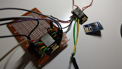
I wanted to test out ESP8266 for a long time. However, I never got it to work until today. There are many tutorials and articles detailed how to make ESP8266 work, but even I followed many of those tutorials step by step mine ESP8266 just didn't work.  It was very frustrating not able to figure out what went wrong.  Anyway, I got it worked today, so it's better for me to write the steps down, not just for blog visitor like you, but also for myself as a good reference later on. Previous three failed attempts... 😒 Different Version of ESP8266 There are many ESP8266 variations, the one I used for this tutorial is ESP8266-12E. Please refer to this page [2] to get more information for ESP8266 variations. ESP8266 Pin Assignment Most of the people probably will solder ESP8266 with metal covers facing up, so I placed a reversed pin assignment on the right side for easier pin reference. Material Needed: ESP8266-12E * 1 Perfboard * 1  Breadboard * 1  Wire

Weekend Project – Arduino Temperature Meter V2

Image
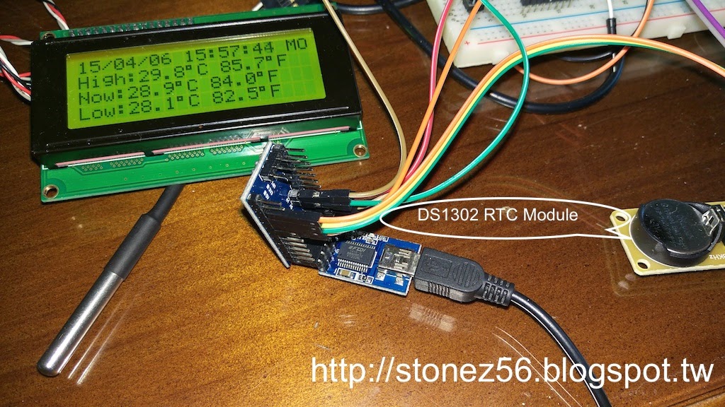
In the last tutorial, I have shown how to make a Temperature Meter which records highest, current, and lowest temperature with Arduino Mini Pro and a DS18B20 temperature probe. One of the readers suggested me if I could record the highest and lowest temperatures measured into EEEPROM, then I won't lost the highest/lowest temperature once power is down. It's a good idea, but  I thought, it would be a greater idea if I kept both time stamp and high/low temperatures! (Writing data to EEEPROM tutorial would be in V3....unfortunately...)  So, I searched Arduino.cc website and found abundant information about DS1302/DS1307 RTC clock modules. Many people mentioned in forums that DS1302/DS1307 are not very precise and tend to draft of few seconds per week/month. However, DS1302 is quite affordable, so I bought 2 pieces from an auction sites and to give it a try.  Reference DS1302RTC data at Arduino.cc Functions added in Temperature V2: Display date/time clock and date of w

Testing Arduino POV (Persistent of Vision) | 試試 Arduino POV (視覺暫留)

Image
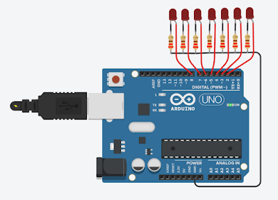
I have been attracted to Arduino POV [1] for quite a while, but I didn't have a chance to actually make it myself.   Luckily, I found this easy to follow Arduino POV tutorial [2] on Instructable.com and within an hour, my son and me made two Arduino POV sets and have fun for the entire afternoon. Material needed for this tutorial: Arduino Nano * 1 (All other kinds of Arduino board will do) LED * 7 220 resistor * 7  Jump wire ~ up to 10 (female to male) Prefboard * 1  Battery pack (If you would like have fun without tethered with USB) Easy Wire Connection as follow: LED1 ~ LED7 negative pin to Prefboard GND Prefboard to Nano(or Uno) GND pin LED1 ~ LED7 postive pin to Nano(or Uno) D2 ~ D8 pin USB power to Nano USB port to supply power (or use a battery back to supply power) Schematic: (I use www.tinkercad.com to draw this schematic below, just in case you interested.) This is a fun a easy project! First, just connect LED cathode(negative) and resist